
Determination of Rippability Classes Through Classical and Geophysical Methods in New Forest Road Excavations, and Their Evaluation in Terms of Cost and Progress Payments
doi: https://doi.org/10.5552/crojfe.2025.2488
volume: issue, issue:
pp: 16
- Author(s):
-
- Diktaş-Bulut Nur
- Gümüş Selçuk
- Karslı Hakan
- Bozlar Tuğba
- Acar Hulusi
- Article category:
- Original scientific paper
- Keywords:
- geophysical methods, forest road, cost-progress payment analysis
Abstract
HTML
Accurately determining soil classes in forest road constructions holds paramount importance in mitigating inconsistencies and disputes in cost and progress payments during and after construction. This study aims to explore the potential of geophysical methods (seismic refraction tomography – SRT, active multichannel analysis of surface waves – A-MASW, electrical resistivity tomography – ERT, and ground-penetrating radar-GPR) in determining the rippability classifications of geological units to be excavated in new forest road constructions, as well as vertical stratification and lateral lithological facies boundaries. This study also conducts a comparative analysis between the cost and progress payment values obtained through classical methods. The study area encompasses six new forest road alignments identified within the Trabzon Regional Directorate of Forestry investment program in Türkiye. For assessing the reliability and validity of the measurements, the Cronbach's alpha test was employed. The equality of the measured variable variances across groups was determined using the Levene’s test, and to determine the source of differences among groups subsequent to the measurements, the Dunnett’s test from multiple comparison tests was utilized. The study revealed disparities between the excavation volumes/class ratios/approximate costs calculated based on soil classes in new forest roads by the forestry administration, the excavation volumes/class ratios/approximate costs realized upon construction completion, and the excavation volumes/class ratios/approximate costs calculated within the scope of this study. The results obtained demonstrated that the combined utilization of SRT, ERT, and A-MASW methods enhanced the reliability of soil characterization and rippability classification when determining rock rippability characteristics in forest road constructions. In this context, it is considered that the additional cost incurred by geophysical engineering measurements can be justifiably met, given the potential benefits, which include more rational planning of investment budgets and cost analyses in new forest road constructions, as well as the facilitation of savings in time, labor, and capital. Furthermore, these measurements are anticipated to contribute to the resolution of potential disagreements between contractors and forestry administrations.
Determination of Rippability Classes Through Classical and Geophysical Methods in New Forest Road Excavations, and Their Evaluation in Terms of Cost and Progress Payments
Nur Diktaş-Bulut, Selçuk Gümüş, Hakan Karslı, Tuğba Bozlar, Hafiz Hulusi Acar
https://doi.org/10.5552/crojfe.2025.2488
Abstract
Accurately determining soil classes in forest road constructions holds paramount importance in mitigating inconsistencies and disputes in cost and progress payments during and after construction. This study aims to explore the potential of geophysical methods (seismic refraction tomography – SRT, active multichannel analysis of surface waves – A-MASW, electrical resistivity tomography – ERT, and ground-penetrating radar-GPR) in determining the rippability classifications of geological units to be excavated in new forest road constructions, as well as vertical stratification and lateral lithological facies boundaries. This study also conducts a comparative analysis between the cost and progress payment values obtained through classical methods. The study area encompasses six new forest road alignments identified within the Trabzon Regional Directorate of Forestry investment program in Türkiye. For assessing the reliability and validity of the measurements, the Cronbach's alpha test was employed. The equality of the measured variable variances across groups was determined using the Levene's test, and to determine the source of differences among groups subsequent to the measurements, the Dunnett's test from multiple comparison tests was utilized. The study revealed disparities between the excavation volumes/class ratios/approximate costs calculated based on soil classes in new forest roads by the forestry administration, the excavation volumes/class ratios/approximate costs realized upon construction completion, and the excavation volumes/class ratios/approximate costs calculated within the scope of this study. The results obtained demonstrated that the combined utilization of SRT, ERT, and A-MASW methods enhanced the reliability of soil characterization and rippability classification when determining rock rippability characteristics in forest road constructions. In this context, it is considered that the additional cost incurred by geophysical engineering measurements can be justifiably met, given the potential benefits, which include more rational planning of investment budgets and cost analyses in new forest road constructions, as well as the facilitation of savings in time, labor, and capital. Furthermore, these measurements are anticipated to contribute to the resolution of potential disagreements between contractors and forestry administrations.
Keywords: geophysical methods, forest road, cost-progress payment analysis
1. Introduction
Forest roads are constructed to efficiently manage and operate forests, protect against diseases and pests, combat wildfires, conduct afforestation and maintenance work, and fulfill the road requirements of villages located within forests. Due to the services they provide, geometric standards, planning, construction techniques, and the challenges and distinct characteristics of their locations, forest roads differ from public roads and village roads constructed for the benefit of the community (Şener 1985).
In Türkiye, the planning and execution of forest road construction is conducted in accordance with the principles outlined in the General Directorate of Forestry Regulation No. 292 on Forest Road Planning, Construction, and Maintenance (GDF 2008). The construction phase of a forest road included in the road network plan begins with its inclusion in the road investment program by relevant authorities one year prior. The estimation of the approximate cost for road construction, following field reconnaissance, is carried out by an approximate cost commission established within forest management directorates. The distribution ratios of excavation volumes to soil classes for preparing the approximate cost of the road, which is applied in the field, are predominantly determined based on surface observations (Dursun 2008). Within this context, the length of forest roads, excavation volumes, and the distribution of excavation volumes according to soil classes are used to estimate the approximate cost for road construction. This process involves the determination of quantities of work included in the approximate cost and is subsequently tendered as a forest road construction project by bidding committees established by Forest Management Directorates. Additionally, in the preparation of measurement tables, factors such as slope gradient at profile points and road width are taken into consideration. In recent years, the on-site application of road alignments and the calculation of approximate costs for road alignments in new forest road constructions by Forest Management Directorates in Türkiye have also been entrusted to independent/independent sworn forestry offices and companies under the framework of the minimum fee schedule announced annually by the Chamber of Forestry Engineers (GDF 2008, CFE 2021).
Forest road excavation works generally constitute the most significant cost component in the construction of low-volume forest roads, and accurately predicting excavation volume is essential for estimating construction costs and ensuring cost control during road construction (Contreras et al. 2012, Gümüş et al. 2003). Excavation costs depend on the lithological and geotechnical conditions of the ground, making the accurate determination of excavation volumes and soil classes crucial during the bidding process (Acar and Karabacak 2012). Incorrect identification of soil classes can lead to encountering hard rocks that require blasting, unexpected landslide-prone areas, and stability issues, all increasing project costs. Geological and geophysical methods can help predict soil characteristics, preventing such challenges (Acar et al. 2003). Erdaş (1997) highlighted the importance of pre-assessing road alignments, including terrain slope, soil properties, and rock qualities, while Gümüş et al. (2003) noted that excavation costs rise as soil transitions to hard rock in forest road construction.
The utilization of geophysical methods has gained importance and prevalence in recent years for assessing the geological and geotechnical attributes of designated road alignments in forest road constructions, both in terms of accuracy and cost-effectiveness (Rao et al. 2004, Soupios et al. 2005, Kurtuluş et al. 2006, Victor and Mamah 2014). The seismic refraction tomography (SRT) method relies on the propagation of elastic waves generated on the surface of the ground or in a shallow borehole, which critically refract at interfaces with velocity differences, propagate along the interfaces, and refract again critically, being recorded by receivers placed in a specific arrangement on the surface (Redpath 1973, Azwin et al. 2013, Rucker 2000, Sheehan et al. 2005). The SRT method is used for mapping the layered structure of the near-surface (<100 m) environment, fractured and weak zones, rippability degrees of rocks, underlying bedrock topography, thickness of overlying materials, depth and topography of slip surfaces in landslide-prone areas, as well as determining the geophysical and geotechnical characteristics of soils and rocks, groundwater table, and soil behavior. The Active Multichannel Analysis of Surface Waves (A-MASW) method involves the analysis of dispersive surface waves and shear wave velocities from seismic data recorded using conventional seismic reflection equipment (Park et al. 1999, Socco and Strobbia 2004, Kanlı et al. 2006, Karslı 2018). Particularly, the A-MASW technique enables to calculate the average shear wave velocity down to a depth level of 30 meters, known as Vs30, which has been recognized nationally (TBEC 2018) and internationally (BSSC 1997, CEN 2004) as the fundamental and reliable method for determining stiffness and strength classifications of soils. In studies related to the determination of road alignments, A-MASW also provides the classification of soil for road excavation, selection of excavation machinery, and thereby consistent preliminary cost estimation, through obtaining S-wave velocity-depth profiles along the crossing (Karslı et al. 2021). Electrical Resistivity Tomography (ERT) is a geophysical method based on the two-dimensional imaging of resistance to electrical current within subsurface materials. It is highly preferred for determining lithological variations, rock weathering, and groundwater content (Dahlin 1996). In the method, current is applied to the ground through two points using stainless electrodes (such as steel, chromium-nickel, etc.), and the voltage difference (potential difference) generated in the ground is measured through two other points. The resistance of the ground is then calculated based on the relationship R=∆V/I (voltage difference/current) according to Ohm's law, and then it is converted to resistivity value, ρ – multiplying with the spreading factor, k – calculated between electrodes using the formula, ρ=k×R. Electrical Resistivity Tomography (ERT) allows for determining the thickness and depth of geological structures, lateral lithological changes, clay content, soil moisture, saline water intrusion, fractured zones, rock weathering degrees, subsurface voids, and the locations of buried waste materials (Dahlin 1996). Ground Penetrating Radar (GPR) is a method developed based on the propagation of electromagnetic waves within the ground. Electromagnetic waves sent into the ground by a transmitter antenna reflect from interfaces between layers with differing electromagnetic impedance, scatter from various objects, and are recorded at the surface by a receiving antenna (Annan 2003). GPR provides high-resolution images of shallow subsurface depths, making it highly successful in detecting subsurface voids, concealed block rocks, weak subsurface zones, fractured structures of rocks, as well as locating cables, pipes, and small-scale scattering elements (Ékes and Firiele 2004). The most significant contribution of GPR measurements is their rapidity, allowing for quick data acquisition and analysis. Thus, road alignments can be efficiently scanned and examined using GPR in a short period.
The objective of this study is to explore the contributions of geophysical methods, including SRT, MASW, ERT, and GPR, in determining the physical, mechanical, geometrical, and geotechnical properties of geological units, thereby providing highly accurate information about the ease or difficulty of excavation in forest road constructions, and to compare cost-progress payment values associated with these methods.
2. Materials and Methods
2.1 Study Area
The study area encompasses the forest road alignments with codes 21, 22, 69, 267, 307, and 315, which are included in the road investment program of the Trabzon Regional Directorate of Forestry. Among these new forest road alignments, road numbers 21 and 22 are located within the Sürmene Forest Management Directorate, road number 69 is situated within the Köprübaşı Forest Management Directorate, road number 267 falls under the Sultanmurat Forest Management Directorate, and roads numbers 307 and 315 are found within the Ağasar Forest Management Directorate (Fig. 1).
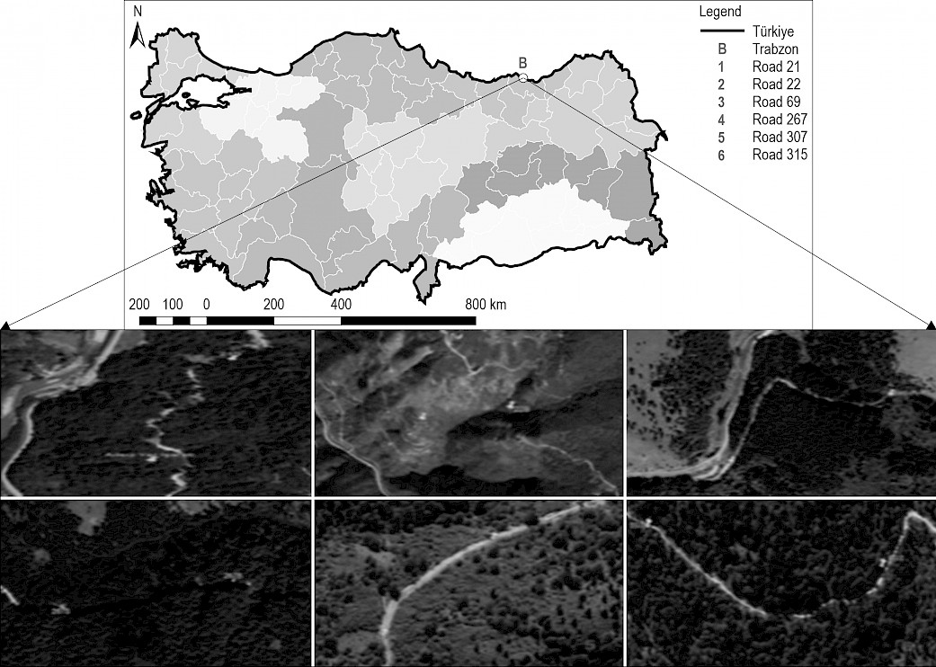
Fig. 1 Study Area (Forest road routes investigated by geophysical methods)
2.2 Selection of Road Alignments
During the selection of road alignments, forest areas encompassing varying slope categories (0–35% and 36–70%), vegetation density (closed forest areas and degraded forest areas), and various subsurface characteristics (soil and rocky) were taken into consideration. A total of six forest road alignments were chosen, with two alignments for each parameter.
2.3 Geophysical Data Acquisition
Geophysical measurements for approximate cost calculation were conducted in 500-meter segments of each road crossing (Table 1). All measurements were taken before the commencement of road construction activities. Consequently, data from SRT, A-MASW, ERT, and GPR were collected for each designated 500-meter section of the six road alignments. The SRT data were gathered along 10 consecutive profiles for each 500-meter crossing section, with five shots per profile (starting, ending, middle, and quarter shots, with three stacks at each shot point). A total of 24 vertical-component receivers (geophones) with a frequency of 4.5 Hz were used for data acquisition. Inversion of the first arrival times of these data were used to obtain SRT sections (2D P-wave velocity map) and to obtain 1D-Vs depth profile (S wave velocity). The ERT data were acquired using a multi-electrode system (48 electrodes) in a Wenner-Schlumberger array. The GPR data were collected using a shielded 300 MHz antenna. The SRT and A-MASW data were processed and evaluated using ZondSt2d software (Kaminskiy 2015), the ERT data using ZondRes2d software (Kaminskiy 2015), and the GPR data was also processed using GRP Slice software (Goodman 2004).
Table 1 Information on geophysical surveys
|
Road code |
Geophysical methods |
Profile length and number of profiles |
Description |
|
21 |
SRT A-MASW ERT GPR |
500 m; 6 profiles for SRT and A-MASW; 3 profiles for ERT; 10 GPR profiles |
Each GPR profile is ~ 50 m |
|
22 |
|||
|
69 |
|||
|
267 |
450 m; 3 profiles for SRT and A-MASW; 3 profiles for ERT; 7 GPR profiles |
||
|
307 |
350 m; 3 profiles for SRT and A-MASW; 3 profiles for ERT;7 GPR profiles |
||
|
315 |
550 m; 6 profiles for SRT and A-MASW; 3 profiles for ERT; 11 GPR profiles |
The SRT and ERT sections obtained from consecutive surveys at each road section were combined and presented to enable an integrated evaluation of the classification of the studied road segment. Topographic variations along the measurement were considered and incorporated into the preparation of SRT and ERT sections. The soil classes were determined based on the SRT sections and 1D Vs-depth profiles, using P and S-wave velocity-rippability tables provided by Caterpillar (2010) and Karslı et al. (2021). Although the study areas mainly consist of volcanic rocks, these rock units can contain inherent void structures, sometimes in the form of caves or fractures and fissures. Both ERT and GPR sections were used to determine the presence of such formations.
2.4 Calculation of Excavation Volumes
Within the scope of the study, the measurement sections for geophysical surveys were determined by obtaining the metric tables of the selected roads for sampling. Following this stage, calculations were carried out to determine the excavation section areas and the excavation volumes between sections in the relevant profiles. After drawing the section areas, considering the depth values of the soil classes (soil, weathered rock, soft rock, hard rock, and very hard rock) determined based on geophysical assessments, the profile areas were separately calculated. Therefore, the calculation method, which uses different class ratios after road construction according to the Forest General Directorate Regulation No. 292, was applied, taking advantage of the excavation slope. The thickness values corresponding to the mentioned classes were determined based on the rippability classification obtained through geophysical measurements. Using the depth values, cross-sections were drawn in Netcad GIS 8.
Rippability classification was performed according to the variation of P-wave velocity in SRT sections along distance and depth, but using the reliability of S-wave velocities in distinguishing soil-rock. Thus, the SRT sections were converted into a layered velocity model (attain of the layer interfaces) with reference to the velocity ranges in Table 2. Therefore, it has been determined at what depth range the rippability will occur.
Table 2 A preliminary seismic velocity-rippability-geotechnical classification for geological units according to both P- and S- wave velocities (Karslı et al. 2021)
|
Vp, km/s |
Vs, km/s |
Rippability |
Geotechnical Explanation |
Excavation / Rippability Explanation |
|
0.3–0.6 |
<0.2 |
Very easy |
Soft / very soft soil |
Easily excavated with excavators |
|
0.6–0.9 |
0.2–0.4 |
Easy |
||
|
0.9–1.5 |
0.4–0.6 |
Moderate |
Solid-very stiff soil |
Excavated with excavators |
|
1.5–2.1 |
0.6–0.8 |
Difficult |
Very stiff-hard soil or weathered / soft rock |
Ripped with ripping device / tools by breaking |
|
2.1–2.4 |
0.8–1.1 |
Very difficult |
Strong rock / very strong-hard rock |
Ripped with compressor or blasting |
|
>2.4 |
>1.1 |
Extremely difficult / nonrippable |
After drawing the section areas and performing calculations, these values were transferred to a calculation table prepared by the authors in Microsoft Excel, and inter-section volume calculations were carried out. To achieve this, both Netcad GIS 8 and Microsoft Excel software were used concurrently on the computer screen, with appropriate window dimensions and positions established.
A comparison was made between the volume values obtained from geophysical measurements and those obtained using the classical method based on the metric table approach. Finally, in conjunction with the excavation values calculated after the completion of road construction for progress payment purposes, the differences between these three values were further statistically evaluated.
2.5 Cost and Statistical Analysis
In addition to the differences identified in excavation volumes, the resulting cost discrepancies were also evaluated. The differences between the determined excavation volume and cost values and the progress payment excavation and cost values were examined to assess whether the cost differences arising from the method developed in this study would cover the differences between the current study cost and the ongoing study survey and application costs.
Statistical analyses were conducted by comparing the values determined through preliminary surveys (both classical and geophysical) with the excavation values obtained upon construction completion. Furthermore, a comparison of the accuracy and costs of the four proposed geophysical methods in soil studies was performed. The reliability and validity of the measurements were assessed using the Cronbach's alpha test. The homogeneity of variance across groups was examined using the Levene's test. The percentage method and descriptive statistics were employed for data evaluation. To identify the source of differences among groups based on measurement results, the Dunnett's Test among multiple comparison tests was used. The Dunnett's Test is a robust test used to compare the mean of one group with the means of other groups under control (Özdamar 1999). Unlike other multiple comparison tests, the Dunnett's test can be employed even if the null hypothesis (H0) is not rejected based on the results of variance analysis (Zar 1999, Özdamar 1999).
3. Results
3.1 Results Related to Geophysical Measurements
For each road route, the sections obtained from the SRT, A-MASW, ERT and GPR measurement results are given in Fig. 2, 3 and 4, respectively, and the holistic evaluations of the sections are presented below. SRT sections are presented to show the P-wave velocity distribution; however, in order to calculate the cut volume and cost of the material to be excavated, they were converted to the layered ground model. 1D-Vs depth profiles were used for geotechnical descriptions of soil and rocks. ERT sections were interpreted considering the resistivity changes of the geological units. Since it is considered in general practice in terms of excavation performance and therefore cost, changes in resistivity values are associated with the strength of the geological units, weathering status, water and clay content. On the other hand, GPR data were collected on profiles of ~ 50 m along each road route, and thus 10 GPR sections were obtained in a route. As combining GPR sections for each route increases the data volume, the apparent quality of the sections deteriorates. For this reason, only sections showing remarkable anomalies (considered to show voids, buried block rock, clay interfaces) are presented for each road route.
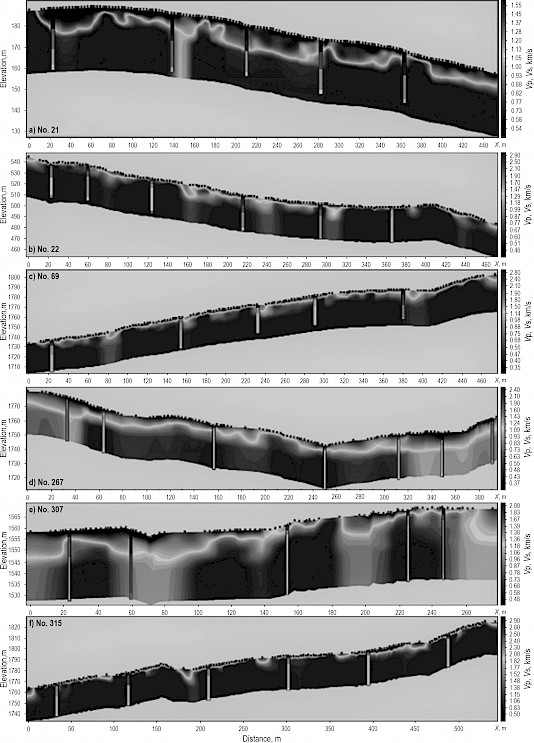
Fig. 2 SRT sections and 1D-Vs profiles (vertical bars on STR section) for each road routed
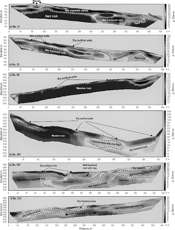
Fig. 3 Interpreted ERT sections for each road route
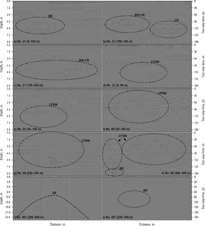
Fig. 4 Selected GPR profiles which include remarkable anomalies from each road routine. The number of each road routine and profile interval are shown on images. Circles on images indicate the anomalies. Vertical lines on (i) show approximate border of the possible void. BR – block reflection, CR – clay reflection, CFRW – clay filling fractured rock with water, VR – void reflection
In forest road codes No. 21 and 315, the results of the SRT and ERT measurements indicate that the area is predominantly composed of rock units. In forest road code No. 21, it is evident that the surface included intermittently easy-to-moderately rippable soil layers with thicknesses ranging from 6 to 8 meters, followed by moderate and difficult rippable rock units immediately beneath. In forest road codes No. 22 and 69, it is observed that on the surface, there are soils units, ranging from 0.5 to 1.0 meter thickness, to easily excavate, followed by layers of moderate, difficult, very difficult, and extremely difficult to excavate rock units underneath. In forest code No. 267, it was determined that on the surface, there were areas of very easy- and easy-to-excavate soil with occasional thicknesses of 5–6 meters, and that immediately below, there were layers of moderate, difficult, and very difficult-to-excavate rock units. In forest road code No. 307, SRT section and 1D Vs-depth profiles reveal the presence of easily excavable soil with occasional thicknesses of 4–5 meters on the surface, followed by medium, difficult, very difficult, and extremely difficult rock layers. In forest road code No. 315, it was determined that the area is predominantly composed of rock units. In all forest roads, the areas seen as hard rock in the SRT and showing decreases in resistivity values in the ERT section, are attributed to the presence of water content within the fractures of the rock. In forest road codes No. 21 and 22, within the identified units characterized by low resistivity on the surface, there are instances of high-resistivity anomalies, denoted by the presence of closures. These closures are presumed to originate from blocky rock structures within the clayey-sandy units. The indications of these blocky structures are observed in GPR sections as hyperbolic and high electromagnetic velocity anomalies. In forest road code No. 307, based on GPR measurements, a potential void structure was identified, particularly in profile between 200 m and 250 m. In forest road codes No. 69, 267 and 315, during the GPR measurements, no void structures were encountered.
3.2 Results Regarding Excavation Volume Calculation
When examining the excavation volumes and class ratios calculated based on soil classes for forest road constructions by the Forest Management Directorates, the excavation volumes and class ratios calculated within the scope of the project, and the excavation volumes and class ratios realized at the end of the construction process (Table 3), differences in excavation volume values and class ratios were observed. For example, on road with code 21, the proportion of soil class within all classes was determined as 75.2% at the end of the construction process. The soil class ratio anticipated by the management (43.7%) differed by 31% from the realized soil class ratio. In other words, the management underestimated the soil class by 31%. The soil class ratio determined by geophysical measurements (79.3%), on the other hand, was 4% higher than the realized class ratio. On the road with code 267, the proportion of rock class within all classes was 11.5% at the end of the construction process. The rock class ratio anticipated by the management (24%) differed by 13% from the realized rock class ratio. The management overestimated the rock class ratio by 13% before the construction process. The rock class ratio determined by geophysical measurements (14.1%), however, was 3% higher than the realized rock class ratio. On the road with code 307, the proportion of soft rock class within all classes was 5% at the end of the construction process. The management predicted a slightly higher soft rock class ratio (5.9%) before the construction process, which is an overestimation of 1% compared to the realized soft rock class ratio. The soft rock class ratio determined by geophysical measurements (9.2%) was overestimated by 5% compared to the realized soft rock class ratio. On the road with code 21, the hard rock class was not determined at the end of the construction process. The management overestimated the hard rock class ratio by 7.5%. According to geophysical measurements, the hard rock class ratio was not estimated. On the road with code 315, the proportion of very hard rock class within all classes was 16.1% at the end of the construction process. The management did not anticipate the very hard rock class. The very hard rock class ratio determined by geophysical measurements (32.7%), however, was overestimated by 17% compared to the very hard rock class ratio realized.
Table 3 Quantity and excavation volumes realized according to class types
|
Road code |
Class* type |
Excavation volume quantity calculated by management, m3 (1) |
Class ratio % |
Excavation volume quantity calculated in project, m3 (2) |
Class ratio % |
Excavation volume realized, m3 (4) |
Class ratio % |
Difference % (4–1) |
Difference % (4–2) |
|
21 |
1 |
2581.490 |
43.7 |
4682.750 |
79.3 |
6095.530 |
75.2 |
31 |
–4 |
|
2 |
1871.895 |
31.7 |
1083.800 |
18.4 |
2010.074 |
24.8 |
–7 |
6 |
|
|
3 |
1009.960 |
17.1 |
137.800 |
2.3 |
0.000 |
0.0 |
–17 |
–2 |
|
|
4 |
440.905 |
7.5 |
0.000 |
0.0 |
0.000 |
0.0 |
–7.5 |
0 |
|
|
5 |
0.000 |
0.0 |
0.000 |
0.0 |
0.000 |
0.0 |
0 |
0 |
|
|
∑ |
5904.250 |
100 |
5904.350 |
100 |
8105.604 |
– |
– |
– |
|
|
22 |
1 |
2013.790 |
41.2 |
830.230 |
16.9 |
606.782 |
14.9 |
–26 |
–2 |
|
2 |
1596.965 |
32.6 |
1926.900 |
39.4 |
261.138 |
6.4 |
–26 |
–33 |
|
|
3 |
742.260 |
15.2 |
1098.020 |
22.4 |
109.880 |
2.7 |
–12 |
–20 |
|
|
4 |
541.185 |
11.0 |
413.860 |
8.5 |
1997.815 |
49.2 |
38 |
41 |
|
|
5 |
0.000 |
0.0 |
625.200 |
12.8 |
1089.967 |
26.8 |
27 |
14 |
|
|
∑ |
4894.200 |
100 |
4894.210 |
100 |
4065.582 |
– |
– |
– |
|
|
69 |
1 |
2875.240 |
41.9 |
1750.480 |
25.5 |
822.616 |
11.5 |
–30 |
–14 |
|
2 |
2221.145 |
32.4 |
2335.200 |
34.0 |
656.649 |
9.2 |
–23 |
–25 |
|
|
3 |
1166.850 |
17.0 |
1537.080 |
22.4 |
819.736 |
11.5 |
–6 |
–11 |
|
|
4 |
600.145 |
8.7 |
465.550 |
6.8 |
4838.499 |
67.8 |
59 |
61 |
|
|
5 |
0.000 |
0.0 |
775.350 |
11.3 |
0.000 |
0.0 |
0 |
–11 |
|
|
∑ |
6863.380 |
100 |
6863.660 |
100 |
7137.500 |
– |
– |
– |
|
|
267 |
1 |
2707.800 |
55.0 |
4182.525 |
84.9 |
3493.168 |
62.5 |
8 |
–22 |
|
2 |
1181.820 |
24.0 |
694.475 |
14.1 |
642.122 |
11.5 |
–13 |
–3 |
|
|
3 |
260.590 |
5.3 |
50.400 |
1.0 |
510.153 |
9.1 |
4 |
8 |
|
|
4 |
568.555 |
11.5 |
0.000 |
0.0 |
859.246 |
15.4 |
4 |
15 |
|
|
5 |
208.530 |
4.2 |
0.000 |
0.0 |
83.842 |
1.5 |
–3 |
2 |
|
|
∑ |
4927.295 |
100 |
4927.400 |
100 |
5588.531 |
– |
– |
– |
|
|
307 |
1 |
814.140 |
18.3 |
2621.550 |
58.8 |
1976.400 |
55.4 |
37 |
–3 |
|
2 |
644.130 |
14.4 |
1257.450 |
28.2 |
177.120 |
5.0 |
–9 |
–23 |
|
|
3 |
263.055 |
5.9 |
412.300 |
9.2 |
177.120 |
5.0 |
–1 |
–4 |
|
|
4 |
1008.295 |
22.6 |
169.450 |
3.8 |
708.480 |
19.8 |
–3 |
16 |
|
|
5 |
1730.930 |
38.8 |
0.000 |
0.0 |
531.360 |
14.9 |
–24 |
15 |
|
|
∑ |
4460.550 |
100 |
4460.750 |
100 |
3570.480 |
– |
– |
– |
|
|
315 |
1 |
3470.182 |
52.9 |
553.800 |
8.4 |
1548.428 |
22.0 |
–31 |
14 |
|
2 |
2019.846 |
30.8 |
1602.520 |
24.4 |
794.311 |
11.3 |
–19 |
–13 |
|
|
3 |
522.416 |
8.0 |
1611.280 |
24.6 |
1581.687 |
22.5 |
15 |
–2 |
|
|
4 |
550.336 |
8.4 |
647.770 |
9.9 |
1980.549 |
28.1 |
20 |
18 |
|
|
5 |
0.000 |
0.0 |
2147.410 |
32.7 |
1132.412 |
16.1 |
– |
–17 |
|
|
∑ |
6562.780 |
100 |
6562.780 |
100 |
7037.387 |
– |
– |
– |
|
|
*1 – Soil; 2 – Weathered rock; 3 – Soft rock; 4 – Hard rock; 5 – Very hard rock |
|||||||||
3.3 Results Regarding Excavation Volume Calculation
In determining the differences between estimated costs and progress payments, cost values for each classification type were evaluated separately. Estimated cost calculations for forest road construction projects by the Forest Management Directorates, approximate costs calculated based on geophysical measurements within the project scope, and the actual progress payment amounts upon completion of construction are provided in Table 4. As evident from the table, there are variations between the calculated costs and the progress payment values. Accordingly, the differences between progress payments and operational approximate costs, as well as differences between progress payments and project costs, for road construction projects numbered 21, 22, 69, 267, 301, and 315 are as follows: ($ 258, $ 1309), ($ 1766, $ 671), ($ 4497, $ 3247), ($ 689, $ 1952), ($ 2618, $ 364), and ($ 4243, $ 317), respectively.
Table 4 Estimated cost and progress payment values according to class types
|
Road code |
Class type* |
Approximate cost calculated by management, $ (1) |
Project approximate cost, $ (2) |
Progress payment, $ (3) |
Cost difference, $ (3–1) |
Cost difference, $ (3–2) |
|
21 |
1 |
1461 |
2651 |
3451 |
1989 |
800 |
|
2 |
1464 |
848 |
1573 |
108 |
725 |
|
|
3 |
1581 |
216 |
0 |
–1582 |
–216 |
|
|
4 |
772 |
0 |
0 |
–773 |
0 |
|
|
5 |
0 |
0 |
0 |
0 |
0 |
|
|
∑ |
5280 |
3715 |
5024 |
–258 |
1309 |
|
|
22 |
1 |
1140 |
470 |
344 |
–797 |
–126 |
|
2 |
1250 |
1508 |
204 |
–1045 |
–1303 |
|
|
3 |
1162 |
1720 |
172 |
–990 |
–1548 |
|
|
4 |
948 |
725 |
3501 |
2553 |
2776 |
|
|
5 |
0 |
1173 |
2045 |
2045 |
872 |
|
|
∑ |
4500 |
5596 |
6266 |
1766 |
671 |
|
|
69 |
1 |
1628 |
991 |
466 |
–1162 |
–525 |
|
2 |
1738 |
1827 |
514 |
–1224 |
–1313 |
|
|
3 |
1827 |
2407 |
1284 |
–544 |
–1123 |
|
|
4 |
1052 |
816 |
8479 |
7427 |
7663 |
|
|
5 |
0 |
1455 |
0 |
0 |
–1455 |
|
|
∑ |
6245 |
7496 |
10743 |
4497 |
3247 |
|
|
267 |
1 |
1533 |
2368 |
1978 |
445 |
–390 |
|
2 |
925 |
543 |
502 |
–422 |
–41 |
|
|
3 |
408 |
79 |
799 |
391 |
720 |
|
|
4 |
996 |
0 |
1506 |
509 |
1506 |
|
|
5 |
391 |
0 |
157 |
–234 |
157 |
|
|
∑ |
4253 |
2990 |
4942 |
689 |
1952 |
|
|
307 |
1 |
461 |
1484 |
1119 |
658 |
–365 |
|
2 |
504 |
984 |
139 |
–365 |
–845 |
|
|
3 |
412 |
646 |
277 |
–135 |
–368 |
|
|
4 |
1767 |
297 |
1242 |
–525 |
945 |
|
|
5 |
3248 |
0 |
997 |
–2251 |
997 |
|
|
∑ |
6392 |
3411 |
3774 |
–2618 |
364 |
|
|
315 |
1 |
1964 |
314 |
877 |
–1088 |
563 |
|
2 |
1580 |
1254 |
622 |
–959 |
–632 |
|
|
3 |
818 |
2523 |
2477 |
1659 |
–46 |
|
|
4 |
964 |
1135 |
3471 |
2506 |
2336 |
|
|
5 |
0 |
4029 |
2125 |
2125 |
–1904 |
|
|
∑ |
5326 |
9255 |
9572 |
4243 |
317 |
|
|
*1 – Soil; 2 – Weathered rock; 3 – Soft rock; 4 – Hard rock; 5 – Very hard rock |
||||||
3.4 Statistical Results of Measurements
The calculated Cronbach's alpha (α) value of 0.837, which is greater than 0.60, indicates that the measurements are reliable and valid (Kalaycı 2014). The skewness (0.309) and kurtosis (0.608) values of the measurements fell within the range of –1 to +1, indicating that the data followed a normal distribution (Büyüköztürk 2020). According to Levene's test, the variances of the groups were homogeneous (Levene Statistic: 1.769, df2 = 25, p = 0.167 > 0.05). In determining the differences in excavation volumes, each soil class type was evaluated separately. According to the results of variance analysis, at a 95% confidence level, no statistically significant difference was found between the calculated excavation volumes in the project and the actual excavation volumes, as well as between the excavation volumes calculated by the management and the actual excavation volumes. On the other hand, based on the Dunnett's Test, it was determined that the project excavation volume values for soil, weathered rock, and very hard rock soil class types were closest to the actual excavation volumes (p = 1.00 for soil class type, p = 0.128 for weathered rock class type, p = 0.987 for very hard rock class type).
The variability in the difference between the approximate cost and progress payment values arises from the fact that the unit cost values for the anticipated and realized soil classes in the progress payment differed. According to the results of variance analysis, at a 95% confidence level, there was not a significant difference between the project-calculated approximate cost and progress payment, as well as between the administration-calculated approximate cost and progress payment. However, based on the Dunnett's Test, it was determined that the project approximate cost values for soil, weathered rock, and very hard rock soil class types were closest to the progress payment values (p = 1.00 for soil class type, p = 0.104 for weathered rock class type, p = 0.939 for very hard rock class type).
3.5 Cost of Geophysical and Classical Methods
When determining soil classes in forest road constructions using seismic, electrical resistivity tomography, and active multi-channel surface wave analysis methods in combination, the field application and estimation of approximate cost for a 500-meter forest road is $1008 (Table 5). When examining the costs of geophysical methods individually, for a 500-meter forest road segment, the cost of seismic refraction tomography method is $360, active multi-channel surface wave analysis is $288, electrical resistivity tomography is $360, and ground-penetrating radar measurement is $300. Additionally, if the planned road segment has dense vegetation cover (such as forest underbrush), the cleaning of these segments and leveling the surface (grading) is required for ground-penetrating radar measurements. This task would incur an approximate cost of $500 for a 500-meter road segment. In this case, the measurement cost of the ground-penetrating radar method would total $800. The measurement cost for all four methods combined is $1808.
If the task of field application and estimation of approximate cost for the forest road segment is outsourced to forestry bureaus and companies using observational methods, according to the minimum wage tariff of the Chamber of Forest Engineers (CFE 2021), the cost of a 500-meter forest road segment would be $469 (Table 5).
Table 5 Cost of geophysical and observational methods
|
Methods |
Section length, m |
Number of profiles |
Unit price, $ |
Total cost, $ |
|
|
Geophysical |
SRT |
500 |
6 |
60 |
360 |
|
A-MASW |
500 |
6 |
48 |
288 |
|
|
ERT |
500 |
3 |
120 |
360 |
|
|
SRT+A-MASW+ERT |
1008 |
||||
|
GPR |
500 |
– |
0.6 |
300 |
|
|
Preparation of Measurement Section (Vegetation Removal, Leveling, etc.) |
500 |
– |
1 |
500 |
|
|
Total GPR Cost |
800 |
||||
|
Total Cost |
1808 |
||||
|
Classical |
Calculation of on-site application and approximate cost of the forest road according to the Minimum Cost Tariff |
469 |
|||
4. Discussion
In this study, a comparison was conducted between the approximate cost and progress payment values prepared by forestry administrations for forest road construction projects and the approximate cost and progress payment values determined through geophysical methods. Upon reviewing both national and international literature, it is evident that geotechnical engineering measurements have been tested in various terrain and soil conditions. However, there are very few studies that specifically focus on the application and comparison of SRT, A-MASW, ERT, and GPR methods in the context of forest road construction, which highlights the significance of this study.
Contreras et al. 2012, Gümüş et al. 2003, Acar and Karabacak 2012 and Acar et al. 2003 found that there were differences in the types of excavation material in their studies. In the study, differences were also identified between the calculated excavation volumes/class ratios based on soil classes by the forestry administration in forest road construction projects, the excavation volumes/class ratios calculated within the scope of the project, and the excavation volumes/class ratios realized at the end of the construction process. Moreover, it was determined that excavation volumes calculated based on geophysical methods for soil classes, such as soil, weathered rock, and very hard rock, were closest to the progress payments.
In the study, it was found that there was no difference in the measurement performance of SRT, ERT, and A-MASW based on soil structure and vegetation cover, and that measurement sensitivity was not affected by soil structure and vegetation cover. However, in measurements conducted with GPR, it was observed that in forests with dense vegetation cover (high canopy closure or dense understorey), disruptive reflections increased and measurement performance decreased.
GPR method is particularly successful in providing high-resolution imaging of vertical layering and lateral discontinuities of geological units from the surface to several meters depth in shallow subsurface investigations (Annan 2005, Petersen et al. 2005). However, concerning the method characteristics, it is essential that the surface for measurements is smooth and that precautions are taken to minimize surface-disturbing effects. Therefore, for GPR measurements to be conducted, measurement profiles (or transects) need to be established and the surface needs to be smoothed within the planned forest road cross-section. In this study, the establishment of measurement profiles in areas with dense vegetation cover and steep terrain required significant labor, time, and cost. Hence, it can be stated that determining excavation classes in forest road construction using GPR may not be very efficient due to decreased measurement performance and data quality in areas with very dense vegetation cover. However, in open and less environmentally impacted areas, GPR can be recommended for control and testing purposes in road alignments.
The ERT sections have provided explanatory information about lithological changes and subsurface water content along the determined road cross-section. Locations with decreased electrical resistivity values mostly indicate the infiltration of surface water into the ground and/or an increase in groundwater content, as well as lateral compression zones and fractured surfaces. Additionally, high resistivity values can characterize rock environments; however, they can also represent subsurface voids and very dry soil units (such as gravel, sand, silty clay products). However, in environments rich in volcanic rocks (a general characteristic of the Black Sea region), the decrease in resistivity values can be attributed to conductive minerals present in both rocks and weathered soil masses. Therefore, directly correlating low resistivity with water content and high resistivity with rock can lead to misconceptions. Hence, while ERT measurements are highly effective and accurate in determining site characteristics and structural changes, they should be used as complementary to seismic methods for determining soil/rock erodibility or classes.
Seismic methods are fundamentally reliant on the physical parameter of »seismic velocity«, which changes entirely based on the properties of the soil/rock, such as stiffness, hardness, compressibility, and porosity. Therefore, they are essential for the classification or grading of excavation areas according to their rippability. Thus, in the present study, the results obtained from seismic methods, which show the distribution of seismic velocity, were taken as the primary reference in defining the rippability characteristics for six different roads. This approach allows us to use increasing seismic velocities as an indicator of increased soil/rock integrity and, consequently, greater difficulty in rippability. In the study, 2D tomographic P-wave (Vp, compression or longitudinal waves) velocity sections were obtained through the seismic refraction technique, and these sections were used to determine the layered structure of the road cross-section and the lateral variations of the geological units based on velocity magnitude. Furthermore, using the A-MASW method, the density and stiffness properties of the geological units in the excavation area could be accurately determined based on the S-wave velocity-depth variation for each profile. Generally, the S-wave (Shear wave) velocity, Vs, effectively defines the stiffness and hardness characteristics of the rock at locations where Vs is greater than 760 m/s. Thus, by considering both Vp and Vs velocities together, the changes in rippability in the excavation areas of the study could be accurately determined.
The SRT results were correlated with the ERT results for each profile. One of the most noteworthy correlations was the relationship between low resistivity areas in ERT sections and high velocities. In such areas, the clear presence of varying degrees of subsurface water (such as moisture, wetness, saturation) and/or geological units containing conductive minerals was considered. Conversely, high resistivity in ERT sections, combined with low velocities in SRT sections, indicated the presence of relatively dry units regardless of whether they were soil or rock. Based on the results of the study, it was concluded that a combination of SRT, ERT, and A-MASW was necessary for determining soil classifications in forest road construction.
Differences were observed between the approximate cost calculations made by the forestry enterprises based on soil classifications for forest road construction, the approximate cost calculations derived from geophysical methods, and the actual progress payment values. It was determined that geophysical method-based approximate cost values for soil classifications, specifically for soil, weathered rock, and very hard rock types, closely matched the progress payment values. The variability in the differences between approximate cost and progress payment values stems from the variations in unit cost values (item values) associated with the projected and realized soil classifications.
5. Conclusions
When determining forest road alignments, factors such as the amount of excavation, production capacities of excavation machinery, loading and transportation systems, geotechnical properties of the excavated geological units, and environmental conditions should be taken into consideration. The application of geophysical methods in this context can provide significant contributions by spatially characterizing the qualities (or classes) of excavated materials and predicting excavation volumes based on the variations of physical parameters, thus enhancing the accuracy of estimating excavation costs.
In this study, the application of geophysical methods (SRT, ERT, A-MASW and GPR) in the determination of forest road alignments was carried out. In this scope, it was evaluated that geophysical methods will provide extremely important contributions in determining more reliably the spatial changes (distance and depth dimension) of the classes of the materials to be excavated in the excavation of forest roads, the estimation of the excavation quantities based on the change of physical parameters and the determination of the excavation cost.
Furthermore, it is undeniable that the prior implementation of geophysical survey studies for forest road alignments included in road network plans would greatly facilitate forest managers during the tender and construction phases. Conducting geophysical studies for forest road alignments that have not been included in the investment program will contribute to reducing investment costs and establishing a scientific knowledge base for soil studies.
In light of this study, it is considered that the additional cost incurred by geophysical engineering measurements would be justifiable for the Forest Administration, given that these measurements can contribute to more rationally planning investment budgets and cost analyses for new forest road constructions, ensuring savings in time, labor, and capital, and aiding in resolving potential disputes between contractors and the forest administration.
Acknowledgements
This study was produced as part of the research project numbered TZN-03.8210, conducted under the Eastern Black Sea Forestry Research Institute Directorate, affiliated with the General Directorate of Forestry of the Ministry of Agriculture and Forestry of the Republic of Türkiye.
6. References
Acar, H.H., Karabacak, M., 2012: The investigation of approximate cost and progress payment for forest road building in Lakes Region of Turkey. Turkish Journal of Forestry 13(1): 21–27. https://doi.org/10.18182/tjf.21878
Acar, H.H., Coşkun, N., Eker, M., 2003: Geophysical investigation of road ground in the construction of village and forest roads, expected environmental and economic benefits. Proceeding of The Eastern Black Sea Region Rural Transport, Settlement Problems and Solutions Symposium, December 18–20, Trabzon, Türkiye, Abstract Book: 68–74.
Annan, A.P., 2003: Ground Penetrating Radar Principles, Procedures & Applications. Sensors & Software Inc., Mississauga, Canada, 1–278. Available at: https://geolportal.sdsu.edu/jiracek/sage/documents/Sensors%20and%20Software%20GPR%20Manual.pdf (Accessed 15 May 2022)
Annan, A.P., 2005: GPR Methods for Hydrogeological Studies. In: Hydrogeophysics (Eds.: Rubin, Y., Hubbard, S.S.), Water Science and Technology Library, vol 50. Springer, Dordrecht. https://doi.org/10.1007/1-4020-3102-5_7
Azwin, I.N., Saad, R., Nordiana, M., 2013: Applying the Seismic Refraction Tomography for Site Characterization. APCBEE Procedia 5: 227–231. https://doi.org/10.1016/j.apcbee.2013.05.039
BSSC, 1997: Building Seismic Safety Council. NEHRP recommended provisions for seismic regulations for new buildings and other structures: Part 1, Provisions (FEMA 302). Building Seismic Safety Council. 334 p. Available at: https://www.nehrp.gov/pdf/fema450provisions.pdf (Accessed 10 July 2022)
Büyüköztürk, Ş., 2020: Sosyal Bilimler İçin Veri Analizi El Kitabı: İstatistik, Araştırma Deseni, SPSS Uygulamaları ve Yorum. 28rd ed., Pegem Akademi, p. 224, Ankara, Türkiye.
CAT, 2010: Caterpillar performance handbook. 40th ed. Caterpillar Inc., Peoria, Illinois, U.S.A.
CEN, 2004: Eurocode 8-design of structures for earthquake resistance. Part 1: General rules. Seismic actions and rules for buildings. European Standard EN 1998-1. European committee for standardization, Brussels. Available at: https://www.phd.eng.br/wp-content/uploads/2015/02/en.1998.1.2004.pdf (Accessed 5 May 2022)
CFE, 2021: Chamber of Forest Engineers. Minimum wage table. Available at: https://eski.ormuh.org.tr/uploads/dosya/2021%20OMO%20Asgari%20%C3%9Ccret%20Tarifesi%20D%C3%BCzenlenmi%C5%9F%20SON%20Hali.pdf (Accessed 15 October 2022)
Contreras, M., Aracena, P., Chung, W., 2012: Improving accuracy in earthwork volume estimation for proposed forest roads using a high-resolution digital elevation model. Croat. J. For. Eng. 33(1): 125–142.
Dahlin, T., 1996: 2D resistivity surveying for environmental and engineering applications. First Break 14(7): 275–283. https://doi.org/10.3997/1365-2397.1996014
Dursun, E., 2008: Orman Yol Geçkilerindaki Zemin Yapısının Jeofizik Yöntemlerle Ortaya Konulması Üzerine Bir Araştırma, Master thesis, Karadeniz Technical University Institute of Science and Technology, Trabzon, Türkiye.
Ékes, C., Friele, P., 2004: Ground penetrating radar and its use in forest road stability analysis. In Proceedings of the Tenth International Conference on Grounds Penetrating Radar, IEEE, Delft, Netherlands, June 21–24, 2008, 639–642.
Erdaş, O., 1997: Forest Roads. v: I–II, Karadeniz Technical University Faculty of Forestry Publication No: 187/25-188/26, Trabzon, Türkiye.
GDF, 2008: General Directorate of Forestry of Türkiye. Planning, Construction and Maintenance of Forest Roads Communiqué No: 292. Ankara, Türkiye. Available at: https://www.ogm.gov.tr/tr/e-kutuphane-sitesi/mevzuat-sitesi/Tebligler/Orman%20Yollar%C4%B1%20Planlamas%C4%B1,%20Yap%C4%B1m%C4%B1%20ve%20Bak%C4%B1m%C4%B1%20(292%20Say%C4%B1l%C4%B1%20Tebli%C4%9F).pdf (Accessed 15 October 2022)
Goodman, D., 2004: GPR-SLICE. Ground Penetrating Radar Imaging Software. User's Manual. California: Geophysical Archaeometry Laboratory.
Gümüş, S., Acar, H.H., Tunay, M., Atesoğlu, A., 2003: Calculation of cut and fill volumes by GIS in forest road projecting. In Proceeding XII World Forestry Congress, Quebec City, Canada, September 21–28, 152–153 p.
Kalaycı, Ş., 2014: SPSS Applied Multivariate Statistical Techniques. Asil Publishing, Ankara, Türkiye, 426 p.
Kanlı, A.I., Tildy, P., Prónay, Z., Pınar, A., Hermann, L., 2006: VS 30 mapping and soil classification for seismic site effect evaluation in Dinar region, SW Turkey. Geophys. J. Int. 165(1): 223–235. https://doi.org/10.1111/j.1365-246X.2006.02882.x
Kaminsky, A., 2015: ZondST2D [Software]. Available at: http://zond-geo.ru/english/zond-software/seismic-tomography/zondst2d/
Karslı, H., 2018: Multi-Channel Surface Wave Analysis (MAWS) Method in Geophysics-Geotechnical Collaboration Process. Geophysical Bulletin 78: 14–48. Available at: https://api.jeofizik.org.tr/uploads/portal/resimler/ekler/9e9dda471b0c838_ek.pdf (Accessed 15 May 2022)
Karslı, H., Babacan, A.E., Şenkaya, M., Gelişli, K., 2021: An evaluation on rippability of geological units by seismic P- and S-wave velocities. Pamukkale University Journal of Engineering Sciences 27(3): 410–419. https://doi.org/ 10.5505/pajes.2020.35920
Kurtuluş, C., Bozkurt, A., Endeş, H., 2006: Local soil conditions of the area between the gulf of Izmit and Lake Sapanca. Proceeding of the 15th International Symposium Ecology, Sunny Beach Resort, Bulgaria, June 5–9.
Özdamar, K., 1999: Statistical Data Analysis with Package Programs-1. 2rd ed.; Kaan Publishing, Eskişehir, Türkiye.
Park, C.B., Miller R.D., Xia J., 1999: Multichannel analysis of surface waves. Geophysics 64(3): 800–808. https://doi.org/10.1190/1.1444590
Petersen, H., Fleige, H., Rabbel, W., Horn, R., 2005: Applicability of geophysical prospecting methods for mapping of soil compaction and variability of soil texture on farm land. J. Plant Nutr. Soil Sci. 168(1): 68–79. https://doi.org/10.1002/jpin.2004.21282
Rao, V.V., Raju, J.S., Rao, B.P., Rao, P.K., 2004: Bed rock investigation by seismic refraction method-a case study. J. Indian Geophys. Union 8(3): 223–228.
Redpath, B.B., 1973: Seismic refraction exploration for engineering site investigations (No. EERL-TR-E-73-4). U. S. Army Engineer Waterways Experiment Station Explosive Excavation Research Laboratory, Livermore, California, USA. https://doi.org/10.2172/4409605
Rucker, M.L., 2000: Applying the Seismic Refraction Technique to Exploration for Transportation Facilities, in Geophysics 2000. The 1st International Conference on the Application of Geophysical Methodologies to Transportation Facilities and Infrastructure, St. Louis, December 11–15, 1–3 p. Phoenix, Arizonam: AMEC Earth & Environmental, Inc.
Sheehan, J.R., Doll, W.E., Mandell, W.A., 2005: An evaluation of methods and available software for seismic refraction tomography analysis. J. Environ. Eng. Geophys. 10(1): 21–34. https://doi.org/10.2113/jeeg10.1.21
Socco, L.V., Strobbia, C., 2004: Surface Wave Methods for near-surface characterisation: a tutorial. Near Surf. Geophys. 2(4): 165–185. https://doi.org/10.3997/1873-0604.2004015
Soupios, P.M., Papazachos, C.B., Vargemezis, G., Fikos, I., 2005: Application of modern seismic methods for geotechnical site characterization. Proceeding of the Int. Workshop in Geoenvironment and Geotechnics, Milos Island, Greece, September 12–14, 163–170 p.
Şener, E., 1985: Development rationality issues of mechanised forest road construction, mechanisation and efficiency in forestry. Proceeding of 1th National Symposium of Mechanisation and Efficiency in Forestry, Publications of the National Productivity Centre, Bolu, Türkiye, July 8–12, 110–128 p.
TBEC, 2008: Turkey Building Earthquake Code. Disaster and Emergency Management Authority of Türkiye. p. 159, Ankara, Türkiye.
Victor, E., Mamah, L., 2014: Geophysical investigation of road failure the case of Opoji in Nigeria. International Journal of Scientific & Engineering Research 5(1): 1769–1779.
Zar, J.H., 1999: Bioistatistical Analysis. 4th Edition, Upper Saddle River, New Jersey, USA, Prentice Hall, p. 663.
© 2025 by the authors. Submitted for possible open access publication under the
terms and conditions of the Creative Commons Attribution (CC BY) license (http://creativecommons.org/licenses/by/4.0/).
Authors' addresses:
Nur Diktaş Bulut, PhD *
e-mail: nurdiktas@yahoo.com
Eastern Black Sea Forestry Research Institute
Department of Forest Enterprise and Economy
61040 Trabzon
TÜRKİYE
Prof. Selçuk Gümüş, PhD
e-mail: sgumus@ktu.edu.tr
Karadeniz Technical University
Faculty of Forestry
Department of Forest Engineering
61030 Trabzon
TÜRKİYE
Prof. Hakan Karslı, PhD
e-mail: hkarsli@ktu.edu.tr
Karadeniz Technical University
Faculty of Engineering
Department of Geophysical Engineering
61030 Trabzon
TÜRKİYE
Tuğba Bozlar, MSc
e-mail: tugbabozlar@gmail.com
Eastern Black Sea Forestry Research Institute
Department of Wood and Non-Wood Forest Product
61040 Trabzon
TÜRKİYE
Prof. Hafiz Hulusi Acar, PhD
e-mail: hafizhulusi.acar@yeniyuzyil.edu.tr
İstanbul Yeni Yüzyıl University
Institute of Health Sciences
Department of Occupational Health and Safety
34010 İstanbul
Türkiye
* Corresponding author
Received: September 28, 2023
Accepted: December 22, 2024
Original scientific paper
11