
A Research of Design, Lateral Stability and Simulation for a Chassis Running in Forest
doi: 10.5552/crojfe.2022.1683
volume: 43, issue:
pp: 18
- Author(s):
-
- Zhu Yue
- Kan Jiangming
- Liu Fenglu
- Article category:
- Original scientific paper
- Keywords:
- forestry chassis, rough terrain, mobility performance, lateral stability, multibody dynamics simulation
Abstract
HTML
Forest roads are short of structured terrain. Individual wheels often cannot contact the ground when conventional chassis is driving, and the mobility is weak. In addition, the lateral rollover usually occurs. In this article, a forestry chassis with a novel articulated structure with three degrees of freedom (FC-3DOF(II)) is proposed. Compared with conventional chassis, the novel articulated structure is designed, which contributes to achieving full-time contact between wheels and ground. The mobility is improved. For the lateral stability, the previous lateral rollover model of chassis is often established by the geometrical position of COG (center of gravity) of the frame. This method is applied with limitations, which is not universal. Therefore, a new accurate lateral rollover model for FC-3DOF(II) is derived, which predicts the lateral stability by analyzing tire contact forces. The new lateral rollover model is more general and recovers the previous model. To verify the theoretical analysis exactly, the virtual prototype of FC-3DOF(II) is established in SolidWorks, and simulations of lateral rollover are carried out in ADAMS. In simulation experiments, the lateral stability is predicted by analyzing tire contact forces when the inclination of terrain is increasing. Two conditions are considered in simulations. The lateral stability of FC-3DOF(II) and FC-3DOF(II) installed rectangular objects. Compared to the simulation and theoretical results, for FC-3DOF(II), the maximum absolute percent difference of the contact force with the theoretical analysis relative to the simulation is only 1.83%. For FC-3DOF(II) installed rectangular objects, the simulation results show that the lateral rollover is caused by the rear up-slope wheel when the inclination of terrain reaches 34°. The theoretical result relative to the simulation is only 2.90%. The maximum absolute percent difference of the contact force with the theoretical analysis relative to the simulation is only 2.50%. Simulation results validate the effectiveness of the proposed lateral rollover model in two conditions.
A Research of Design, Lateral Stability and Simulation for a Chassis Running in Forest
Yue Zhu, Jiangming Kan, Fenglu Liu
Abstract
Forest roads are short of structured terrain. Individual wheels often cannot contact the ground when conventional chassis is driving, and the mobility is weak. In addition, the lateral rollover usually occurs. In this article, a forestry chassis with a novel articulated structure with three degrees of freedom (FC-3DOF(II)) is proposed. Compared with conventional chassis, the novel articulated structure is designed, which contributes to achieving full-time contact between wheels and ground. The mobility is improved. For the lateral stability, the previous lateral rollover model of chassis is often established by the geometrical position of COG (center of gravity) of the frame. This method is applied with limitations, which is not universal. Therefore, a new accurate lateral rollover model for FC-3DOF(II) is derived, which predicts the lateral stability by analyzing tire contact forces. The new lateral rollover model is more general and recovers the previous model. To verify the theoretical analysis exactly, the virtual prototype of FC-3DOF(II) is established in SolidWorks, and simulations of lateral rollover are carried out in ADAMS. In simulation experiments, the lateral stability is predicted by analyzing tire contact forces when the inclination of terrain is increasing. Two conditions are considered in simulations. The lateral stability of FC-3DOF(II) and FC-3DOF(II) installed rectangular objects. Compared to the simulation and theoretical results, for FC-3DOF(II), the maximum absolute percent difference of the contact force with the theoretical analysis relative to the simulation is only 1.83%. For FC-3DOF(II) installed rectangular objects, the simulation results show that the lateral rollover is caused by the rear up-slope wheel when the inclination of terrain reaches 34°. The theoretical result relative to the simulation is only 2.90%. The maximum absolute percent difference of the contact force with the theoretical analysis relative to the simulation is only 2.50%. Simulation results validate the effectiveness of the proposed lateral rollover model in two conditions.
Keywords: forestry chassis, rough terrain, mobility performance, lateral stability, multibody dynamics simulation
1. Introduction
Most of the earth’s surface is inaccessible to general vehicles which are mostly even if we refer to tractors, cars, or trains. Conventional vehicles only run on regular ground instead of uneven terrain (Franceschetti et al. 2014, Li and Kang 2020, Štícha et al. 2018). Forest roads are short of structured terrain. Individual wheels often cannot contact the ground when conventional chassis is driving, and the mobility is weak (Alamdari and Krovi 2016, Ishigami et al. 2014, Franceschetti et al. 2014). In addition, the lateral rollover usually occurs (Abubakar et al. 2010, Gravalos et al. 2011, Ayers et al. 2018). As a result, a great deal of research has focused on mobility and lateral stability for chassis running in uneven terrain, such as forestry chassis (Chen et al. 2020, Zhu et al. 2018, Lideskog et al. 2015, Manzone and Calvo 2018).
Conventional wheeled chassis have serious mobility and lateral stability limitations in rough terrain (Zhu et al. 2015, Zhu et al. 2017). Researchers have a growing interest in developing off-road chassis in recent years. The studies performed by Potau et al. (2011) and Comellas et al. (2013) quantified the ability of overcoming obstacles by using different configurations of vehicle with bogies. Bogies are robust, but a drawback is heavy weight. More serious, active bogies often cause lateral rollover (Pijuan et al. 2012). Sun et al. (2017) designed a new type of mobile robot that could be applied on both flat and rugged terrains. Based on the stability analysis of the robot obstacle crossing, the obstacle climbing strategies have also been acquired. The structure of mobile robot is significant in developing forestry chassis. Gelin et al. (2020) introduced a forestry chassis which improved operator’s comfort and off-road capability through pendulum arm technology. Significantly, the center of gravity of the chassis can be controlled by pendulum arm within limits, which enhances the lateral stability of running in uneven terrain. Structure design and traction mobility of multi-posture wheel-legs bionic walking wheels applied in sand terrain were analyzed by Zhang et al. (2020). The bionic walking wheels can imitate the interaction between ostrich toe and sand, and have active sand-crossing function by changing wheel-legs posture. The stability of wheel-legs posture was also analyzed, considering that some vehicles needed to drive on special terrain, such as stairs. Ge and Wang (2014) proposed a model of a quadruped eccentric wheel chassis, which achieved excellent performance, even exhibiting the ability to climb stairs. However, the lateral rollover is easy to occur when the vehicle surmounts obstacle at a high speed. Moreover, compared with general vehicles, tractors are widely used in forest. An asymmetric tractor-harvester was investigated by Choi et al. (2017). An analysis of stability by modified mathematical model for asymmetric tractor-harvester system was obtained. The modified mathematical model was useful for predicting the overturning angle of the asymmetric tractor-equipment system, and verified that a movement of the center of gravity coordinates had a critical effect on its stability. Li et al. (2016) proposed a model tractor that is designated to pass over typical forestry road surfaces. Parameter sensitivity for tractor lateral stability against overturn on random road surfaces was researched, which is implied by statistical analysis of relative factors. However, the study on tractor lateral stability does not absolutely reveal the intrinsic numerical relationship between sensitive parameters. A tractor with an oscillating front axle was proposed by Demšar et al. (2012). The oscillating front axle can enhance the adaptability of the wheels to the road within limits. A mathematical model and a numerical simulation of the stability of the tractor in relation to its position on a slope was analyzed. This research concludes that the distance between the center of gravity and ground has the biggest effect on stability. However, the study assumes that the inertia and mass of front axle can be ignored. In addition, articulated chassis have the characteristic of a small steering radius and are suitable for working in narrow spaces. This advantage is often applied in designing a chassis to work in forests. A study that analyzed the obstacle-surpassing ability of a forestry chassis with an articulated structure (FC-3DOF) was presented by Zhu and Kan (2016). However, poor ride comfort was present when crossing obstacles. Therefore, a 6-wheels driven chassis with an articulated structure and installed luffing wheel-legs (FC-3DOF&LW) was designed by Zhu et al. (2018). Chassis ride comfort is enhanced by controlling luffing wheel-legs when crossing obstacles. Nevertheless, for the articulated structure, the pitching motion (rolling in y axis, shown in Fig. 3) of the front and rear frames is a passive mechanism, which requires the chassis to be equipped with 6 or 8 wheels. The size of chassis is bigger due to the number of wheels, which leads to the lack of flexibility. What was worse, FC-3DOF&LW cannot find the instantaneous center of wheel rotation with turning, resulting in too much lateral friction. Based on the above reason, a forestry chassis with a novel articulated structure with three degrees of freedom (FC-3DOF(II)) is proposed in this paper. Compared with above chassis, the novel articulated structure is designed with three degrees of freedom (rolling in x, y, z axis, shown in Fig. 3). Significantly, the rolling in y and z direction is an active structure, and in x direction passive, which is different from the two above articulated structures. Due to the active control rolling y axis, FC-3DOF(Ⅱ) is a 4-wheels chassis. The size of FC-3DOF(II) is smaller than the above 6-wheels chassis (FC-3DOF or FC-3DOF&LW). FC-3DOF(II) has the instantaneous center of wheel rotation with turning, which reduces considerably lateral friction. Then, the relative position of the front and rear frame can be changed by driving the novel articulated structure, which contributes to achieving full-time contact between wheels and ground. The mobility is thus improved. In addition, although the articulated chassis is similar to the tractors fitted with front axle pivot and swing axle, the stability analysis using the above mathematical model is insufficient due to the assumptions that the inertia and mass of front axle are ignored. As a result, a new accurate lateral rollover model of FC-3DOF(II) is derived. The new model predicts the lateral stability by analyzing tire contact forces, which is different from the previous model established by the geometrical position of the frames GOC (center of gravity). The new lateral rollover model is more general and recovers the previous model. To verify the theoretical analysis exactly, the virtual prototype of FC-3DOF(II) is established in SolidWorks, and simulations of lateral rollover are carried out in ADAMS. Two conditions are considered in simulations. The lateral stability of FC-3DOF(II) and FC-3DOF(II) installed rectangular objects. Compared to the simulation and theoretical results, for FC-3DOF(II), the maximum absolute percent difference of the contact force with the theoretical analysis relative to the simulation is only 1.83%. For FC-3DOF(II) installed rectangular objects, the simulation results show that the lateral rollover is caused by the rear up-slope wheel when the inclination of terrain reaches 34°. The theoretical result relative to the simulation is only 2.90%. The maximum absolute percent difference of the contact force with the theoretical analysis relative to the simulation is only 2.50%. Simulation results validate the effectiveness of the proposed lateral rollover model in two conditions.
2. Design of FC-3DOF(II)
2.1 Structure of FC-3DOF(II)
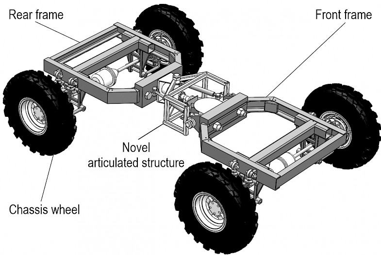
Fig. 1 Structure of FC-3DOF(II)
FC-3DOF(II) is designed to run in the rough terrain of the forest, as shown in Fig. 1. It consists of two frames and four wheels. The two frames are connected by a novel articulated structure with three degrees of freedom. The traditional articulated structure is often single degree (rolling in z axis, as shown in Fig. 3) or two degrees of freedom (rolling in x, z axis, as shown in Fig. 3). Individual wheels often cannot contact the ground when the chassis with traditional articulated structure moves on irregular terrain. The mobility is weak. The novel articulated structure proposed has three degrees of freedom (rolling in x, y, z axis), which can achieve full-time contact between wheels and ground. The mobility of running in uneven terrain is enhanced. Significantly, FC-3DOF(II) is an improved chassis compared with an original FC-3DOF&LW (Zhu et al. 2018). FC-3DOF(II) enhances flexibility by reducing the chassis size and the number of wheels.
2.2 Novel Articulated Structure with Three Degrees of Freedom
The articulated structure is a mechanism that is often applied in engineering vehicles to make a turn. The characteristic of a small steering radius is suitable for working in forest where the space is incredibly narrow. However, the terrain is often uneven in forest where chassis with traditional articulated structures is challenging to adapt. As a result, an articulated structure with three degrees of freedom was proposed for FC-3DOF&LW in previous research. For the articulated structure in FC-3DOF&LW, the pitching motion (rolling in y axis, as shown in Fig. 3) of the front and rear frames is a passive mechanism (Zhu et al. 2018). Therefore, the piching motion of frames will occur automatically under the force of gravity when the chassis is installed with 4 wheels. It is necessary for the chassis to be equipped with 6 or 8 wheels. The size of chassis is bigger due to the number of wheels, which leads to the lack of flexibility. In addition, the instantaneous center of wheel rotation (ICWR) is located at the contact point between the wheel and the ground for conventional 4-wheels chassis. The wheels rotate around the ICWR when the chassis is turning, such as FC-3DOF(II), which generates less friction. However, the ICWR for the rear frame of FC-3DOF&LW is located between the wheels. The wheels slide around ICWR when the chassis is turning, which creates greater friction (as shown in Fig. 2). To solve the above problems, a novel articulated structure with three degrees of freedom is proposed. Fig. 3 shows the novel articulated structure with three degrees of freedom, which can roll in three axises (x, y, and z axis). The rolling in z axis is controlled actively by hydraulic cylinder 5 and hydraulic cylinder 8, and the rolling in y axis is drived by pitching structure 2, which can be controled actively by transmission system. The transmission system consists of transmission gear 9, rotating component 4, winch 11 and block 12, which can be rotated by servo motor 10. The rolling in x axis is a passive structure. Significantly, compared with the original articulated structure in FC-3DOF&LW, the active control rolling y axis is achieved through the novel articulated structure. Due to the active control rolling y axis, FC-3DOF(II) is a 4-wheels chassis. The pitch motion (rolling in y axis) of the front and rear frames is shown with (a), (b), (c) and (d) in Fig. 3. Both active and passive control are applied in the novel articulated structure, which improves the capacity to adapt to terrain and ensures full-time contact between wheels and ground for driving in a complex road environment.
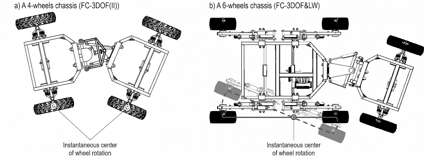
Fig. 2 Sketch of making a chassis turn
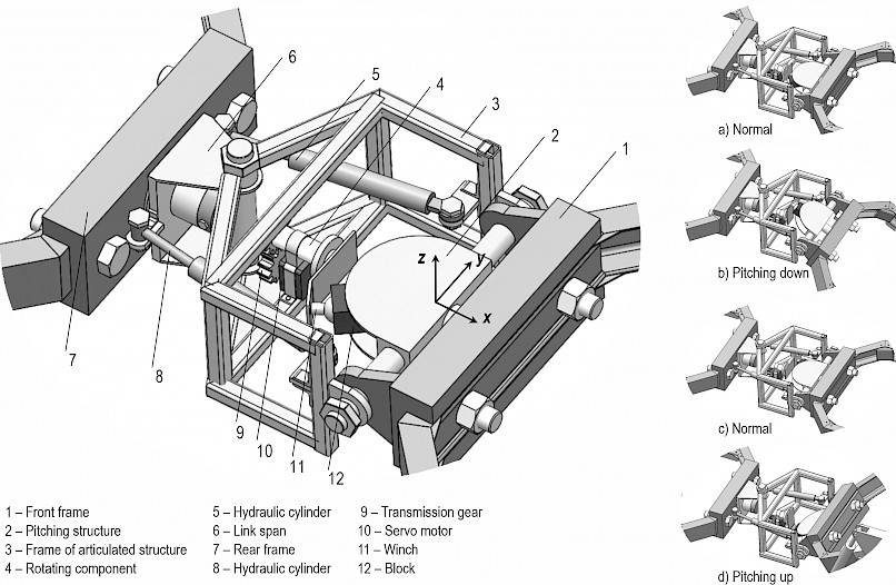
Fig. 3 The novel articulated structure with three degrees of freedom
3. Chassis Lateral Stability
It is little wonder that the chassis applied in forestry is particularly susceptible to rollover, when considering its typically high center of gravity (COG) position coupled with large external loads arising from attached implements and front-end-loaders large torque outputs, and operation on rough terrain. Therefore, the lateral stability is crucial for the forestry chassis.
3.1 Previous Lateral Rollover Initiation Model
Tractors fitted with front axle pivot and swing axle are often used in agricultural and forestry activities. The commonly accepted model assumes that the lateral instability is initiated when the COG of the tractor, excluding the front axle and wheels, is directly above the line AB (Chisholm 1979, Gibson et al. 1971, Gibson and Biller 1974) (as shown in Fig. 4).
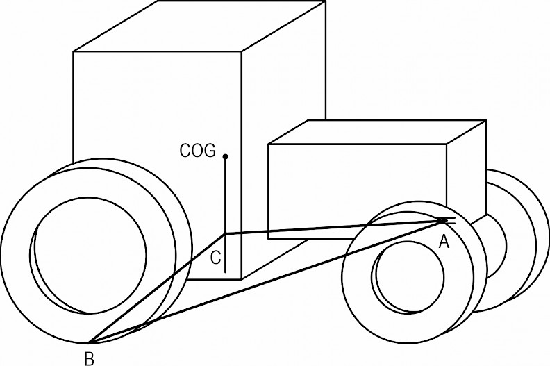
Fig. 4 Schematic of a tractor fitted with front axle pivot and swing axle
Based on the above assumptions, the lateral roll angle θmax will result in the rollover initiation when COG of the tractor is on the verge of rollover about AB. According to Fig. 5, the lateral roll angle θmax can be expressed as follows:
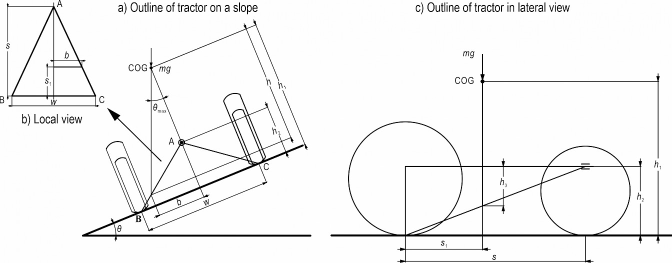
Fig. 5 Schematic of a tractor on a slope
As shown in Fig. 5(b), the distance b between projection for the COG on ABC plane and the midline for ABC plane can be obtained.
 (1)
(1)
In Fig. 5(c), h3 can be expressed as follows:
 (2)
(2)
In Fig. 5(a) – (c), h can be expressed as follows:
 (3)
(3)
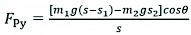
The lateral roll angle θmax shown in Fig. 5(a) can be expressed as follows:
 (4)
(4)
As a result, substituting equation (1), (2), (3) into (4), the following equation is obtained:
 (5)
(5)
However, the previous lateral rollover initiation model is not physically accurate. The front axle pivot point, to which the tractor is connected and constrained, is a hinge with an axis of rotation parallel to the longitudinal axis of the tractor, as shown in Fig. 4. Therefore, the hinge axis AB is not collinear with the real front pivot, which is the reason why the tractor cannot roll laterally only about the line AB. It seems that the existing original model does not account correctly for the coupling between the bodies nor permits the front axle body to move. Furthermore, the tractor GOC is not often to be located along the mid-plane of the body. Although the structure of FC-3DOF(II) is similar to the tractors fitted with front axle pivot and swing axle, the previous lateral rollover initiation model, which has some shortcomings, is not always accurate for FC-3DOF(II). As a result, it will be necessary to develop a new accurate lateral rollover model for FC-3DOF(II).
3.2 Lateral Rollover for FC-3DOF(II)
FC-3DOF (II) runs in rough terrain of the forest, which often causes a problem of lateral rollover. As a result, a novel lateral rollover model for FC-3DOF(II) is derived below. An equivalent model and corresponding geometry are shown in Fig. 6. The key assumptions used in developing the current model are presented in three parts: 1) The articulated joint is frictionless; 2) The inclination angle increases quasi-statically (dynamic effects can be ignored); 3) The GOC is not on the mid-plane of FC-3DOF(II).

Fig. 6 Schematic of FC-3DOF (II)
Based on the equivalent model and corresponding geometry, a simplified entire model of FC-3DOF(II) as viewed in the y–z plane is shown in Fig. 7. Therefore, the combined force FF applying moment equilibrium can be expressed as follows:
 (6)
(6)
 (7)
(7)
Fig. 7 Simplified entire model of FC-3DOF (II)
Similarly, the combined force FR can be obtained as follows:
 (8)
(8)
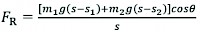 (9)
(9)
It is also noted that the combined forces FF (and FR) at the front and rear result from individual type forces at the contact location, thus
 (10)
(10)
Similarly
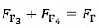 (11)
(11)
A simplified separate model of FC-3DOF(II) as viewed in global coordinate system is shown in Fig. 8. Progressing to equilibrium of the separate bodies, then, for static equilibrium in the x direction of rear frame, the following is obtained:
 (12)
(12)
And in the y direction
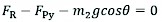 (13)
(13)
Moment equilibrium is obtained as follows:
 (14)
(14)
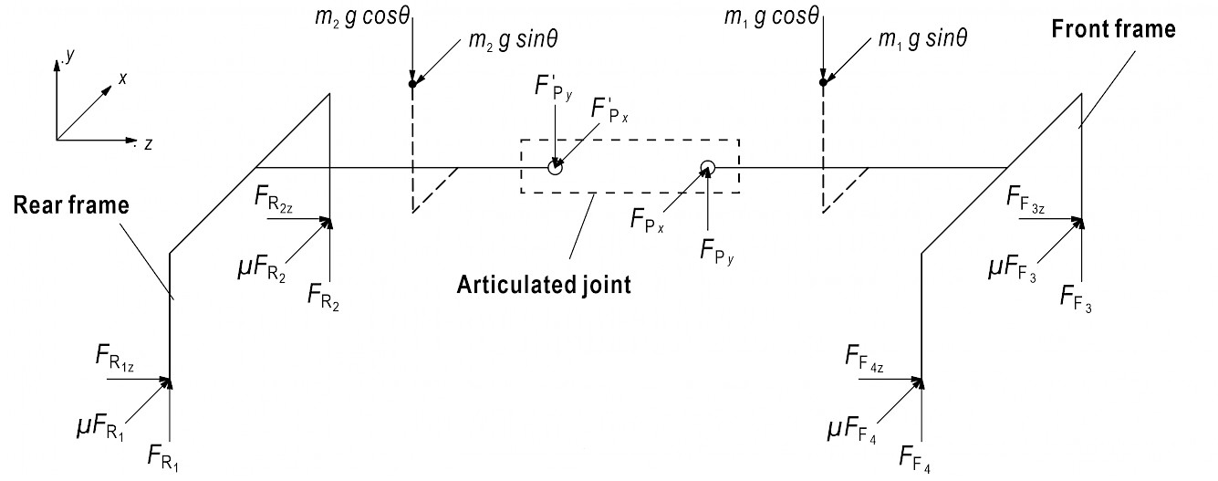
Fig. 8 Simplified separate model of FC-3DOF(II)
Similarly, static equilibrium in the x direction of front frame can be expressed as follows:
 (15)
(15)
And in the y direction
 (16)
(16)
Moment equilibrium is obtained as follows:
 (17)
(17)
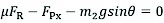
Substituting equation (9) into (12), especially tanθ=μ, the following equation is obtained:
 (18)
(18)
Similarly, substituting equation (9) into (13), the following equation is obtained:
 (19)
(19)
As a result, substituting equation (18), (19) into equation (14) allows the rear up-slope type contact force to be calculated as follows:
 (20)
(20)
Similarly, substituting equation (18) and (19) into equation (17) allows the front up-slope type contact force to be expressed as follows:
 (21)
(21)
Equations (20) and (21) describe how the contact force of up-slope varies depending on the type with the degree of inclination increasing or decreasing. Furthermore, similar expressions can be presented for the down-slope tires. Substituting equation (20) and (9) into equation (10), the following equation is obtained:
 (22)
(22)
Substituting equation (21) and (7) into equation (11), the followting equation is obtained:
 (23)
(23)
It is obvious that, according to the model, the conditions of rollover for FC-3DOF(II) will begin when the front or rear up-slope tire contact force decreases to zero. Thus, the classification is expressed by FR2=0, FF3≠0 or FR2≠0, FF3=0. As a result, FR2=0, FF3≠0 can be described by Equation (20)=0 with Equation (21)≠0.
From Equation (20)
 (24)
(24)
Simplifying and rearranging permits the instability angle to be calculated as follows:
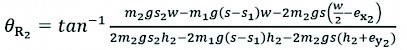 (25)
(25)
Similarly, for Equation (21)
 (26)
(26)
Simplifying and rearranging permits the instability angle to be calculated as follows:
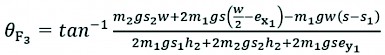 (27)
(27)
Therefore, lateral rollover initiation model can be established by combining Eq. (25) with Eq. (27). The model determines whether the instability is induced by front or rear up-slope wheel. In addition, for the simplified case applied in previous lateral rollover initiation model, m1=0, ex1=0, ex2=0, ey1=0 and s1=s2, h2+ey2=h1.
Substituting the simplified case into Eq. (25), θR2 defines the instability angle as 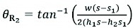 and Eq. (5) is recovered, showing that the novel model accounts for the coupling of the bodies.
4. Simulation Experiments and Results Analysis
4.1 Establishment of Simulation
In order to verify the theoretical analysis of the lateral rollover model for FC-3DOF(II), the virtual prototype of FC-3DOF(II) has been established in SolidWorks (version 2020, Dassault Systèmes S. A., France), and simulations are carried out in ADAMS (version 2013, Mechanical Dynamics Inc., USA) that is applied in multibody dynamics simulation. Increasing the inclination of terrain is considered to describe the lateral stability of FC-3DOF(II), which can be analyzed by the forces of the front or rear up-terrain wheel. In the simulation process, the angular velocity of terrain inclination is increasing slowly, about 0.002 rad/s, by which the effect of motion can be ignored and it can be regarded as the quasi-static condition; the basic parameters are shown in Table 1. Tires of chassis are based on Fiala model, and the parameters are shown in Table 2.
Table 1 Basic parameters of FC-3DOF(II) in simulation
|
Parameter |
Unit |
Value |
|
Length |
mm |
2260 |
|
Width |
mm |
1580 |
|
Wheel diameter |
mm |
660 |
|
Wheel width |
mm |
160 |
|
Mass |
kg |
510 |
Table 2 Parameters of tires
|
Parameter |
Unit |
Value |
|
Vertical stiffness |
N/mm |
310 |
|
Vertical damping |
N/(mm/s) |
3.1 |
|
CSLIP |
N/mm |
1000 |
|
CALPHA |
N/rad |
800 |
|
Static friction coefficient |
– |
0.3 |
|
Rolling resistance coefficient |
– |
0.025 |
4.2 Simulation of Lateral Rollover for FC-3DOF(II)
To describe the lateral rollover for FC-3DOF(II), a simulation model that includes chassis and terrain is built in ADAMS. Especially, the simulation when the FC-3DOF(II) is running in uneven road is presented by increasing the inclination of terrain. As a result, the instability can be analyzed by the forces of the front or rear up-terrain wheel. The simulation model is shown in Fig. 9(a). With the inclination increasing, the forces of wheels for 3DOF(II) are changing, which will result in the danger of rollover. Furthermore, the rollover for the chassis installed articulated joints, such as FC-3DOF(II), is obviously more likely to occur with running in rough terrain. The reason for rollover is susceptible to be affected by the COG position of front or rear frame, and even by the coupling of the bodies. A 10° inclination of terrain is shown in Fig. 9(b). The inclination of 20° and 30° is shown, respectively, in Fig. 9(c) and Fig. 9(d).
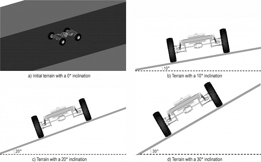
Fig. 9 Simulation of FC-3DOF(II) in ADAMS
Based on the smaller angular velocity of terrain inclination, 0.002 rad/s, the time needed to reach 10°, 20°, 30° is approximately 88s, 175s, 262s. Therefore, the simulation time is 90 s, 180 s, 270 s, respectively, and the number of steps is 9000, 18,000, 27,000, as shown in Fig. 9(b), 9(c) and 9(d). Especially, the FC-3DOF(II) is stable when the inclination of terrain reaches 10°, as shown in Fig. 9(b). The slight lateral slip occurred at the inclination of terrain of 20°, as shown in Fig. 9(c). The FC-3DOF(II) has obviously slipped with the 30° inclination of terrain, but the lateral stability is superior in Fig. 9(d). As a result, the position of COG is relevant to vehicle stability. The COG for FC-3DOF(II) without cabs or equipment is lower than for general vehicle, which means superior lateral stability.
4.3 Simulation of Lateral Rollover for FC-3DOF(II) Installed Rectangular Objects
To verify the theoretical analysis, which involves the lateral rollover in the »The lateral rollover for FC-3DOF(II)« section, a simulation model is built in ADAMS, as shown in Fig. 10. Rectangular objects are separately installed on the front and rear frames to replace the cabs or equipment, which contributes to simulating the real condition and is similar to the model described in Fig. 6(b). In addition, the basic parameters of the FC-3DOF(II) installed rectangular objects are shown in Table 3. The main parameters of tires are consistent with Table 2, but static friction coefficient is 0.7 to prevent the lateral slip. A wide range of lateral slip will lead to the termination of simulation, which affects the data collection of the wheel force. A 10° inclination of terrain is shown in Fig. 11(a). The inclination of 20° and 30° is shown in Fig. 11(c) and Fig. 11(d), respectively. Furthermore, the inclination of 35° is shown in Fig. 11(d).
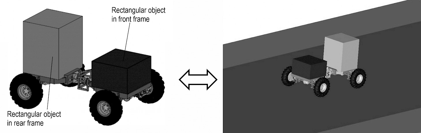
Fig. 10 A model of FC-3DOF(II) installed rectangular objects in ADAMS
Table 3 Basic parameters of frame installed rectangular objects
|
Parameters |
Rectangular object in front frame |
Rectangular object in rear frame |
||
|
Unit |
Value |
Unit |
Value |
|
|
Length |
mm |
820 |
mm |
820 |
|
Width |
mm |
772 |
mm |
772 |
|
Height |
mm |
500 |
mm |
1000 |
|
Mass |
kg |
2485 |
kg |
4970 |
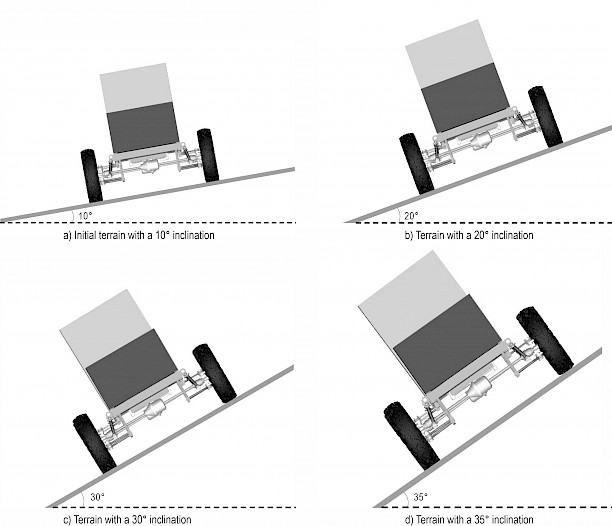
Fig. 11 Simulation of FC-3DOF(II) installed rectangular objects in ADAMS
5. Discussion of Simulation Results
5.1 FC-3DOF(II)
The simulation results are considered in two conditions, FC-3DOF(II) and FC-3DOF(II) installed rectangular objects. For FC-3DOF(II), the contact forces between wheels and terrain in vertical direction are shown in Fig. 12. The simulation results show that the contact force of FR1 is rising with the increase of the inclination degree. The contact of FF4 is similar to FR1. On the contrary, the contact forces of FR2 and FF3 are falling with the increase of the inclination degree. Because of applying the same front and rear frame structure, the trend of the contact forces FR1 and FF4 (FR2 and FF3) is nearly consistent. However, the difference of the contact forces FR1 and FF4 (FR2 and FF3) occur because of the asymmetry of the articulated position, which provides the roll in x direction (as shown in Fig. 3) between the front and rear frames. The contact forces FR2 and FF3 of up-slope wheels in vertical direction are about 750 N when the terrain inclination reaches 30°. The FC-3DOF(II) is stable, which can be analyzed by the existing contact forces. In addition, the contact forces FR1 and FF4 are about 1430 N when the terrain inclination reaches 30°. The position of COG is relevant to vehicle stability. The COG for FC-3DOF(II) without any objects is lower than for general vehicle, which means superior lateral stability.

Fig. 12 Contact forces of wheels in vertical direction for FC-3DOF(II)
Fig. 13 shows the contrast results of contact forces FR1, FR2, FF3 and FF4, which are analyzed between the theoretical and simulation results. The theoretical results are from the above Eqs. (22), (20), (21) and (23) presented in the section »Lateral rollover for FC-3DOF(II)«. In terms of the contact forces FR1, FF4 of the down-slope wheels, shown in Fig. 13(a) and (d), the maximum absolute percent difference between the contact force and the theoretical analysis relative to the simulation is observed with FR1, which can be obtained by using the formula |(F2–F1)/(F1)|×100%, and the value is 1.83%. This means that the theoretical results are almost consistent with the simulation results. The contact forces FR2 and FF3 of the up-slope wheels are shown in Fig. 13(b) and (c), and can be described as the lateral rollover indicator with the increase of the inclination degree. The contact forces FR2 and FF3 of up-slope wheels in the vertical direction are about 750N when the terrain inclination reaches 30°. This demonstrates that the FC-3DOF(II) is stable due to the existing contact forces. In addition, the theoretical results of contact forces FR2 and FF3 are more consistent with the simulation results.
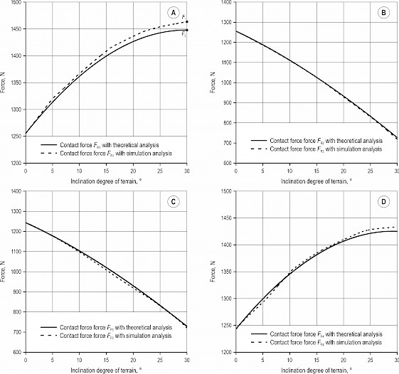
Fig. 13 Differences of contact forces between theoretical and simulation results for FC-3DOF(II)
5.2 FC-3DOF(II) Installed Rectangular Objects
For FC-3DOF(II) installed rectangular objects, the contact forces between wheels and terrain in vertical direction are shown in Fig. 14. The trend of the contact forces between the FC-3DOF(II) installed and uninstalled rectangular objects is consistent. The contact forces FR1 and FF4 are rising, while FR2 and FF3 are decreasing with the increase of the inclination degree. Due to separate installation of rectangular objects of different masses between the front and rear frames, the contact force FR1 is about 42000 N, and FF3 is about 31000 N when the terrain inclination reaches 35°. Furthermore, the contact force FF3 of up-slope wheel is about 30 N when the terrain inclination reaches 35°. However, the contact force FR2 of up-slope wheel is 0 N when the terrain inclination reaches 34°. It means that the FC-3DOF(II) installed rectangular objects are unstable at this time. The lateral rollover is caused by the rear up-slope wheel. The lateral rollover will occur.
Fig. 14 Contact forces of wheels in vertical direction for FC-3DOF(II) installed rectangular objects
Similarly, the contrast results of contact forces FR1, FR2, FF3 and FF4, shown in Fig. 15, are analyzed between the theoretical and simulation results. In Fig. 15(a) and (d), the contact forces FR1 and FF4 based on the theoretical and simulation results are almost consistent. Referring to the above FC-3DOF(II), the maximum absolute percent difference of the contact force for FC-3DOF(II) installed rectangular objects occurs by FF4 with the theoretical analysis relative to the simulation, which can be obtained by using the formula |(F2–F1)/(F1)|×100%. The value is only 2.50%. Furthermore, the simulation results of the contact forces FR2 and FF3 that can be regarded as the lateral rollover indicator are also similar with theoretical results, as shown in Fig. 15(b) and (c). The theoretical and simulated results of FR2 are both 0 N when the terrain inclination reaches 35°, but FF3 is not 0 N. Therefore, the lateral rollover is caused by the rear up-slope wheel. In addition, the simulation results show that the lateral rollover will occur when the terrain inclination reaches 34°. The theoretical result relative to the simulation is only 2.90%, which can be obtained by using the formula |(D2–D1)/(D1)|×100% (as shown in Fig. 15(b)). As a result, the position of COG is relevant to vehicle stability. The stability of FC-3DOF(II) can be analyzed by the proposed lateral rollover model established in the section »Lateral rollover for FC-3DOF(II)«.
Fig. 15 Contrasts of contact forces between theoretical and simulation results for FC-3DOF(II) installed rectangular objects
6. Conclusions
This paper proposes FC-3DOF(II) as a novel chassis driving in forestry terrain. A novel articulated structure with three degrees of freedom is described. The design provides an idea for enhancing mobility for the off-road chassis, such as forestry chassis, by increasing the degree of freedom and active control of bodies. In addition, the lateral rollover model, especially for the chassis with significant front mass, is derived, which can be used for analyzing the lateral stability of a chassis that consists of two frames connected by an articulated structure. It is also suitable for tractors fitted with front axle pivot and swing axle. For the above chassis, the lateral rollover is dependent on the position of the individual frame (the front or rear frame) COG, and not the total COG as previously assumed and accepted. The results encourage the separate determination of chassis mass properties pertaining to the front and rear frames so that lateral stability behavior can be accurately assessed. The model also permits the estimation of tire contact forces.
The results can be used for vehicle designing and stability analysis. The results also provide some foundation for future development of sensory devices that could inform vehicle operators of danger levels.
Acknowledgments
The author(s) disclosed receipt of the following financial support for the research, authorship, and/or publication of this article: This work was supported by National Natural Science Foundation of China (Grant No. 52102422), the Research Funds for Young Teachers of Fujian Education Department (Grant No. KLA19019A) and the Research Fund for Young Teachers of Fujian Agriculture and Forestry University (Grant No. 71201800207).
7. References
Abubakar, M., Ahmad, D., Akande, F., 2010: A Review of Farm Tractor Overturning Accidents and Safety. Pertanika Journal of Science and Technology 18(2): 377–385.
Alamdari, A., Krovi, V., 2016: Design of articulated leg-wheel subsystem by kinetostatic optimization. Mechanism and Machine Theory 100: 222–234. https://doi.org/10.1016/j.mechmachtheory.2016.02.010
Ayers, P., Khorsandi, F., Wang, X., Araujo, G., 2018: ROPS designs to protect operators during agricultural tractor rollovers. Journal of Terramechanics 75: 49–55. https://doi.org/10.1016/j.jterra.2017.05.003
Chen, Y., Mao, E., Li, W., Zhang, S., Song, Z., Yang, S., Chen, J., 2020: Design and experiment of a high-clearance self-propelled sprayer chassis. International Journal of Agricultural and Biological Engineering 13(2): 71–80. https://doi.org/10.25165/j.ijabe.20201302.5262
Chisholm, C., 1979: A mathematical model of tractor overturning and impact behavior. Journal of Agricultural Engineering Research 24(4): 375–394. https://doi.org/10.1016/0021-8634(79)90079-9
Choi, K., Kim, S.-M., Hong, S., 2017: Analysis of Static Stability by Modified Mathematical Model for Asymmetric Tractor-Harvester System: Changes in Lateral Overturning Angle by Movement of Center of Gravity Coordinates. Journal of Biosystems Engineering 42(3): 127–135. https://doi.org/10.5307/JBE.2017.42.3.127
Comellas, M., Pijuan, J., Potau, X., Nogues, M., Roca, J., 2013: Efficiency sensitivity analysis of a hydrostatic transmission for an off-road multiple axle vehicle. International Journal of Automotive Technology 14(1): 151–161. https://doi.org/10.1007/s12239-013-0017-z
Demšar, I, Bernik, R., Duhovnik, J., 2012: A Mathematical Model and Numerical Simulation of the Static Stability of a Tractor. Agriculturae Conspectus Scientificus 77(3): 143–150.
Franceschetti, B., Lenain R., Rondelli, V., 2014: Comparison between a rollover tractor dynamic model and actual lateral tests. Biosystems Engineering 127(1): 79–91. https://doi.org/10.1016/j.biosystemseng.2014.08.010
Franceschetti, B., Rondelli, V., Ciuffoli, A., 2019: Comparing the influence of Roll-Over Protective Structure type on tractor lateral stability. Safety Science 115: 42–50. https://doi.org/10.1016/j.ssci.2019.01.028
Ge, G., Wang, Y., 2014: On Obstacle Crossing Research for Quadruped Eccentric Wheel-Legged Robot[J]. Journal of Southwest China Normal University (Natural Science Edition) 39(10): 96–99. https://doi.org/10.13718/j.cnki.xsxb.2014.10.019
Gelin, O., Henriksen, F., Volungholen, R., Bjorheden, R., 2020: Improved operator comfort and off-road capability through pendulum arm technology. Journal of Terramechanics 90: 41–48. https://doi.org/10.1016/j.jterra.2020.01.003
Gibson, H.G., Elliott, K.C., Persson, S.P.E., 1971: Side slope stability of articulated-frame logging tractors. Journal of Terramechanics 8(2): 65–79. https://doi.org/10.1016/0022-4898(71)90006-1
Gibson, H.G., Biller, C.J., 1974: Side-slope stability of logging tractors and forwarders. Transactions of the ASAE 17(2): 245–250.
Gravalos, I., Gialamas, T., Loutridis, S., Moshou, D., Kateris, D., Xyradakis, P., Tsiropoulos, Z., 2011: An experimental study on the impact of the rear track width on the stability of agricultural tractors using a test bench. Journal of Terramechanics 48(4): 319–323. https://doi.org/10.1016/j.jterra.2011.04.003
Ishigami, G., Iagnemma, K., Overholt, J., Hudas, G., 2014: Design, Development, and Mobility Evaluation of an Omnidirectional Mobile Robot for Rough Terrain. Journal of Field Robotics 32(6): 880–896. https://doi.org/10.1002/rob.21557
Li, Z., Mitsuoka, M., Inoue, E., Okayasu, T., Hirai, Y., Zhu, Z., 2016: Parameter sensitivity for tractor lateral stability against Phase I overturn on random road surfaces. Biosystems Engineering 150: 10–23. https://doi.org/10.1016/j.biosystemseng.2016.07.004
Li, W., Kang, F., 2020: Design and Analysis of Steering and Lifting Mechanisms for Forestry Vehicle Chassis. Mathematical Problems in Engineering: 1–16. https://doi.org/10.1155/2020/5971746
Lideskog, H., Karlberg, M., Bergsten, U., 2015: Development of a research vehicle platform to improve productivity and value-extraction in forestry. Procedia CIRP 38: 68–73. https://doi.org/10.1016/j.procir.2015.07.014
Manzone, M., Calvo, A., 2018: Trailer Overturning during Wood Transportation: an Experimental Investigation of Effects of Trailer Joint Point and Frame Structure. Croat. j. for. eng. 39(1): 97–108.
Pijuan, J., Comellas, M., Nogués, M., Roca, J., Potau, X., 2012: Active bogies and chassis levelling for a vehicle operating in rough terrain. Journal of Terramechanics 49(3–4): 161–171. https://doi.org/10.1016/j.jterra.2012.03.001
Potau, X., Comellas, M., Nogues, M., Roca, J., 2011: Comparison of different bogie configurations for a vehicle operating in rough terrain. Journal of Terramechanics 48(1): 75–84. https://doi.org/10.1016/j.jterra.2010.06.002
Sun, T., Xiang, X., Su, W., Wu, H., Song, Y., 2017: A transformable wheel-legged mobile robot: Design, analysis and experiment. Robotics and Autonomous Systems 98: 30–41. https://doi.org/10.1016/j.robot.2017.09.008
Štícha, V., Holuša, J., Sloup, R., Macků, J., Trombik, J., 2018: A Mobile Hydraulic Winch for Use in Small-Scale Forestry. Croat. j. for. eng. 39(2): 205–212.
Zhang, R., Pang, H., Ji, Q., Li, G., Dong, W., Wen, L., Li, J., 2020: Structure design and traction trafficability analysis of multi-posture wheel-legs bionic walking wheels for sand terrain. Journal of Terramechanics 91: 31–43. https://doi.org/10.1016/j.jterra.2020.05.001
Zhu, Y., Kan, J., Xu, D., Liu, J., 2015: A review on the chassis of the forest machine. Forest Engineering 31(2): 97–102.
Zhu, Y., Kan, J.M., 2016: The design of forestry chassis with articulated body of three degrees of freedom and analysis of its obstacle surpassing ability. Journal of Beijing Forestry University 38(5): 126–132.
Zhu, Y., Kan, J., Xu, D., 2017: The design of a forestry chassis with an articulated body with three degrees of freedom. UPB Scientific Bulletin, Series D: Mechanical Engineering 79(1): 19–30.
Zhu, Y., Kan, J., Li, W., Kang, F., 2018: Strategies of traversing obstacles and the simulation for a forestry chassis. International Journal of Advanced Robotic Systems 15(3): 1–13. https://doi.org/10.1177/1729881418773903
Zhu, Y., Kan, J., Li, W., Kang, F., 2018: A novel forestry chassis with an articulated body with 3 degrees of freedom and installed luffing wheel-legs. Advances in Mechanical Engineering 10(1): 1–10. https://doi.org/10.1177/1687814017747101
© 2022 by the authors. Submitted for possible open access publication under the
terms and conditions of the Creative Commons Attribution (CC BY) license (http://creativecommons.org/licenses/by/4.0/).
Authors’ addresses:
Yue Zhu, PhD
e-mail: zhuyue@fafu.edu.cn
Fujian Agriculture and Forestry University
College of Transportation and Civil Engineering
No. 15 Shangxiadian Road
Cangshan District, Fujian
CHINA
Prof. Jiangming Kan, PhD *
e-mail: kanjm@bjfu.edu.cn
Beijing Forestry University
School of Technology
No. 35 Tsinghua East Road
Haidian District, Beijing
CHINA
Fenglu Liu, PhD
e-mail: liufenglu39@fafu.edu.cn
Fujian Agriculture and Forestry University
College of Mechanical and Electrical Engineering
No. 15 Shangxiadian Road
Cangshan District, Fujian
CHINA
* Corresponding author
Received: April 29, 2021
Accepted: February 18, 2022
Original scientific paper