
Exploring the Design of Highly Energy Efficient Forestry Cranes using Gravity Compensation
doi: 10.5552/crojfe.2022.1303
volume: 43, issue:
pp: 15
- Author(s):
-
- Mendoza-Trejo Omar
- López Rojas Arturo D.
- Morales Daniel Ortiz
- Lindroos Ola
- Cruz-Villar Carlos A.
- La Hera Pedro
- Article category:
- Original scientific paper
- Keywords:
- cranes design, forwarder crane, energy consumption, gravity compensation, counterweights
Abstract
HTML
Although most mechanized forestry work relies heavily on cranes for handling logs along the supply chain, there has been little research on how to improve cranes design. In addition, the available research has mainly focused on improving current designs, so there is a lack of application of modern methods for designing cranes with improved efficiency.
This paper analyzes how a mechanical engineering design method, known as gravity compensation, can be used to make a new generation of highly energy efficient forestry cranes. To introduce this design approach, a standard forwarder crane with two booms is used as a model system on which to apply gravity compensation concepts. The design methodology follows a procedure based on physics and mathematical optimization, with the objective of minimizing the energy needed to move the crane by using gravity compensation via counterweights. To this end, we considered to minimize mechanical power, because this quantity relates to how fuel and hydraulic fluid are converted into mechanical motion.
This analysis suggests that using gravity compensation could reduce energy consumption due to crane work by 27%, at the cost of increasing the crane total mass by 57%. Thus, the original crane mass of 559 kg increases to 879 kg after applying gravity compensation with counterweights. However, overall reductions in energy consumption would depend on both the crane work and the extraction distance. The greater the extraction distance, the lower the total savings. However, energy consumption savings of around 2% could be achieved even with an extraction distance of 1 km.
From a design perspective, this study emphasized the need to consider gravity compensation in the design philosophy of forestry cranes, not only for its ability to minimize energy consumption, but also due to all the inherited properties it provides. This initial study concludes that designing cranes with a combination of gravity compensation concepts could yield a new generation of highly energy efficient cranes with energy savings exceeding those reported here.
Exploring the Design of Highly Energy Efficient Forestry Cranes using Gravity Compensation
Omar Mendoza-Trejo, Arturo D. López Rojas, Daniel Ortiz Morales, Ola Lindroos, Carlos A. Cruz-Villar, Pedro La Hera
Abstract
Although most mechanized forestry work relies heavily on cranes for handling logs along the supply chain, there has been little research on how to improve cranes design. In addition, the available research has mainly focused on improving current designs, so there is a lack of application of modern methods for designing cranes with improved efficiency.
This paper analyzes how a mechanical engineering design method, known as gravity compensation, can be used to make a new generation of highly energy efficient forestry cranes. To introduce this design approach, a standard forwarder crane with two booms is used as a model system on which to apply gravity compensation concepts. The design methodology follows a procedure based on physics and mathematical optimization, with the objective of minimizing the energy needed to move the crane by using gravity compensation via counterweights. To this end, we considered to minimize mechanical power, because this quantity relates to how fuel and hydraulic fluid are converted into mechanical motion.
This analysis suggests that using gravity compensation could reduce energy consumption due to crane work by 27%, at the cost of increasing the crane total mass by 57%. Thus, the original crane mass of 559 kg increases to 879 kg after applying gravity compensation with counterweights. However, overall reductions in energy consumption would depend on both the crane work and the extraction distance. The greater the extraction distance, the lower the total savings. However, energy consumption savings of around 2% could be achieved even with an extraction distance of 1 km.
From a design perspective, this study emphasized the need to consider gravity compensation in the design philosophy of forestry cranes, not only for its ability to minimize energy consumption, but also due to all the inherited properties it provides. This initial study concludes that designing cranes with a combination of gravity compensation concepts could yield a new generation of highly energy efficient cranes with energy savings exceeding those reported here.
Keywords: cranes design, forwarder crane, energy consumption, gravity compensation, counterweights
1. Introduction
1.1 Overview
The physical work environment, the human operators experience, the way in which the work is organized, and the available technology are all important factors to consider when seeking to improve performance and productivity in forest operations (Häggström and Lindroos 2016, Malinen et al. 2018). However, as mentioned in (Dong et al. 2020), it could be sometimes more relevant to focus only on the technological aspects of the work processes such as improvements in forestry crane designs.
In Scandinavian forest operations, forwarder and harvester cranes stand as the heart of timber harvesting using the mechanized cut-to-length (CTL) method (Lundbäck et al. 2021), where the harvester cuts trees to desired lengths within the harvest area and then the forwarder loads logs and transports them to the road-side landing.
At present, a major task of forestry crane operators is to control the crane to ensure that logs are lifted safely, quickly, and easily. Under this scenario, productivity depends on maintaining a good working tempo, and efficiency is achieved by minimizing energy consumption (which in turn minimizes fuel consumption and emissions). However, due to the size, weight, and difficulty of controlling forestry cranes, maintaining a trade-off between low energy consumption while increasing productivity is not readily available at the hands of machine operators. Therefore, in order to improve performance and facilitate operators work, machine manufacturers attempt to provide solutions by constantly adapting to advances in technology (Pagnussat et al. 2020).
According to current developments, there are two main concepts for reducing the energy consumption and increasing productivity of forestry cranes:
Þ the first involves the design of smart hydraulic technology using pressure feedback control software (EATON 2019). These systems reduce the crane oscillations due to structural flexibilities and abrupt motions. Smoother motions remove high pressure build up in the cylinders and thus reduce high energy peaks (Riazi et al. 2015, Riazi et al. 2017). Examples of this technology include John Deere’s Smooth Boom Control and Komatsu’s Smart Flow, both of which use commercially available »intelligent hydraulic valves« (John Deere 2012, Komatsu Forest AB 2017)
Þ the second is the control of crane motions using smart automation software. An initial version, scientifically known as Cartesian control, exists on the market (Spong et al. 2006), where the crane operator controls the tip of the crane instead of each individual boom cylinder. This method is more intuitive for machine operators and helps avoiding unnecessary motions, thus reducing energy losses. Examples of this technology include John Deere’s Intelligent Boom Control, Komatsu Forest Smart Crane, HIAB’s Crane Tip Control, and many other examples sold by consultancy firms around Scandinavia (Manner et al. 2019, Technion 2017, Lindroos et al. 2015).
Recent reports suggest that combining these technologies can increase productivity by 5% on average (Manner et al. 2019). However, forestry is in the early stages of technology adoption. As research shows, higher gains in productivity can be expected using more advanced automation features (Kalmari et al. 2017, Nurmi and Mattila 2017, Ortiz Morales et al. 2014, La Hera et al 2021).
On the other hand, as mentioned before, when working with forestry cranes, increased productivity does not necessarily translate into reduced energy consumption. On the contrary, with the current mechanical design principles applied in industry, increasing productivity may also increase energy consumption, and thus fuel consumption. It is therefore also important to focus on the energy consumption when designing forestry cranes.
According to physics, the energy consumption of a crane is a quantitative property associated to its weight, inertias, and the path motion velocity. Software solutions can influence crane motion, but not other physical quantities such as weight. Thus, substantial reductions in energy consumption cannot be achieved by software alone, which warrants that new crane designs should be considered. However, despite the importance of cranes in mechanized logging, to the best of our knowledge, only a few published articles addressed the issue of improving forestry cranes design (Gerasimov and Siounev 2000, Lindroos et al. 2008). To address this gap, modern methods for redesigning forestry cranes to improve energy efficiency have been explored in this work.
1.2 Problem Formulation
To put the biggest drawback of current forestry cranes design into perspective, Fig. 1 shows a schematic depiction of a standard forwarder crane whose total weight is denoted as WT. The total force exerted by the main boom cylinder is denoted by Fc. According to the first principle laws, to perform any motion, Fc is the result of the sum of two different forces:
Þ the static part, i.e., the force needed to hold the crane weight WT.
Þ the dynamic part, i.e., the force needed to produce a motion at a certain speed and acceleration.
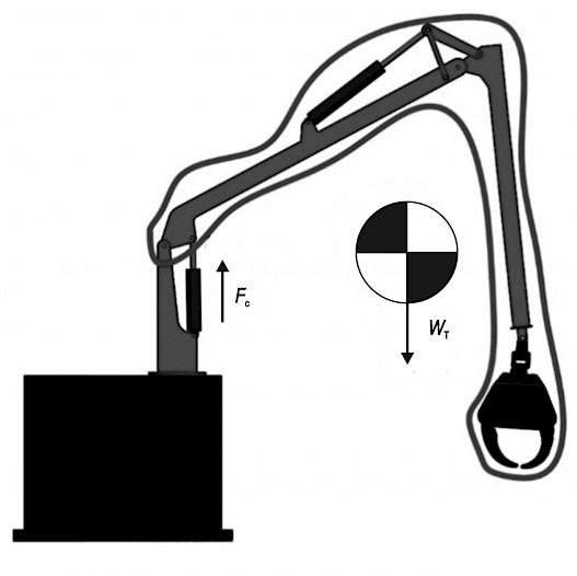
Fig. 1 Static analysis of a forestry crane
The static part typically accounts as the largest portion of Fc, often exceeding 70% of the total (Manring 2005). This implies that software solutions that can influence motion are left to optimize a small portion of the remaining dynamic force.
Therefore, a crane with the architecture shown in Fig. 1 will inevitably spend most of its energy to hold its own weight. Thus, in order to reach substantial reductions in energy consumption, the influence of static forces must be reduced. This can only be achieved by modifying the architecture and mechanical design of cranes. However, modifying the design philosophy of forestry cranes is quite a scarce research area.
1.3 Main Proposition
Gravity compensation (GC) is a well-known mechanical engineering approach widely used in the robotics and automation industry to reduce the effects of gravity, making a mechanical system ideally weightless (Arakelian 2016, Lu et al. 2011). When a mechanical system reaches this ideal state, the actuators (motors, cylinders, etc.) require only dynamic force to perform motion. According to research (Arakelian 2016), GC can reach energy savings in ranges above 70%, because the actuators ideally do not require to compensate static forces. The quantities of energy saving achieved using GC are in ranges that other methods cannot closely match. This is the main reason why most advanced industrial robot manipulators feature this design concept.
Various design concepts for gravity compensation are available in literature. The three principal groups to design gravity compensated systems include:
Þ counterweights, where additional masses are added to counterbalance the main weight (Gosselin 2008, Lowen et al. 1983), as shown on the left of Fig. 2
Þ passive elements, where spring/damper couples are added to generate forces that equal the main weight (Briot and Arakelian 2015), as shown on the right of Fig. 2
Þ auxiliary actuators, where either pneumatic or hydraulic actuators are added to generate forces that equal the main weight (Boisclair et al. 2016, Yamamoto et al. 2010).
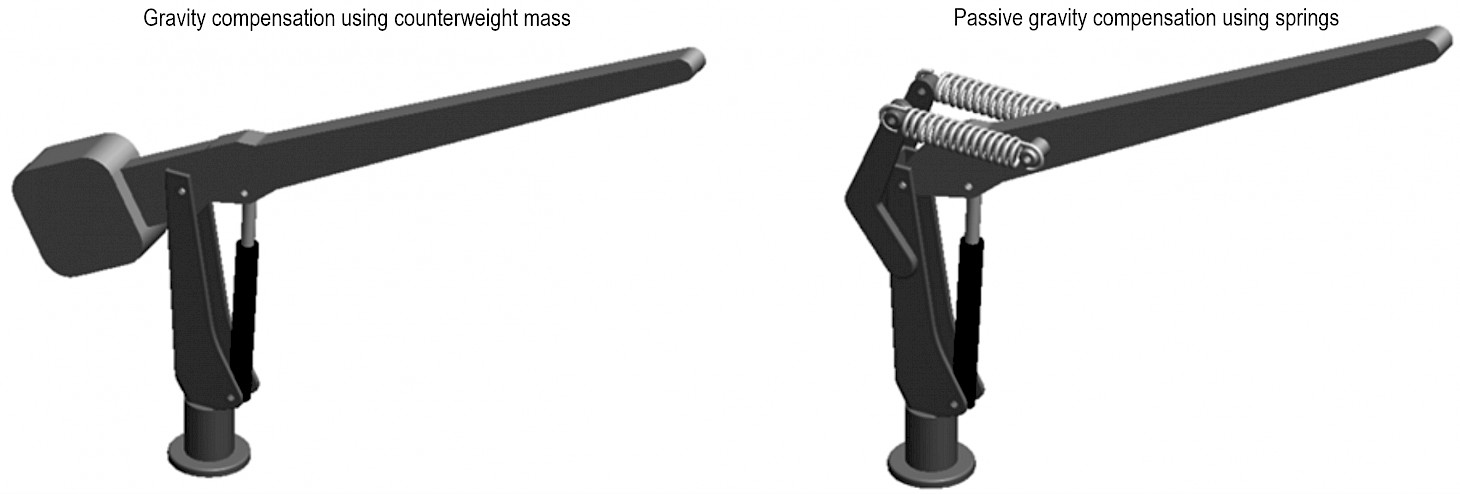
Fig. 2 Examples of gravity compensation for a single link
Although GC has been widely used to minimize energy consumption in mechanical systems, to the best of our knowledge, this is the first time that it has been considered for forestry applications.
It is noteworthy that GC has been used extensively in the robotics industry for tasks where robots are stationary, that is, robots do not have to move around within a certain area. Unlike industrial robots, work with forestry cranes considers felling trees or collecting logs at various locations, so the energy consumption of the vehicle when driving must also be considered.
Further to the above, the purpose of this article was to investigate the application of gravity compensation for designing highly energy efficient forestry cranes, where counterweights were considered as a first case study. To accomplish this purpose, two main points are presented:
Þ a design procedure for a gravity compensated crane using counterweights, where only mechanical parameters related to the crane were taken into account
Þ an energy consumption evaluation for two scenarios: 1) crane work, and 2) crane work plus the motion of the vehicle.
The results obtained demonstrate the potential advantages of GC in the design of highly energy efficient forestry cranes, and reveal some factors that will have to be considered when implementing the proposed design method in industry.
2. Materials and Methods
2.1 Materials
The application of gravity compensation often starts from an initial design of a standard mechanical system without GC. Referring to Fig. 3, our study considered a crane having two links and a grapple mounted at its tip, which is a common design for small and medium-sized forwarders.
To formalize the notation used in this article, Fig. 3 presents a sketch of the standard crane. It has three degrees of freedom for the motions of the base, inner boom, and outer boom. The angular position for the degrees of freedom are denoted as qi having i = [1, 2, 3], where qi denotes the angle for the base, q2 for the inner boom, and q3 for the outer boom. All parameters for angles, lengths and masses use the international system of units (SI). Initially, this crane was developed using CAD modeling software to provide base information about dimensions for each link, as well as its weights and inertias. As shown in Fig. 4, the dimensions of the links are denoted as L1 for the main boom and L2 for the outer boom, respectively. The distance to the center of masses is denoted as d1 for the main boom and d2 for the outer boom. The masses for this crane are presented in section 3. –
In addition to CAD modeling, Matlab/Simulink was used to perform simulation tests (The Mathworks 1990). To this end, all dynamic equations of this crane were programmed inside Matlab in order to have a virtual simulator. Simulations give data about motion, including link positions and velocities, as well as the cylinder forces. This data set was used to calculate energy of motion, which was then used to compare the performance of a standard crane against a gravity compensated crane.
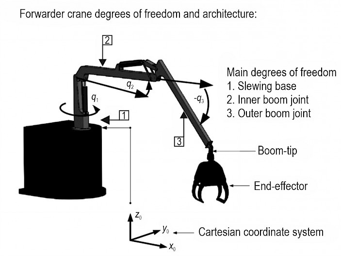
Fig. 3 Components of a forwarder crane and their generalized coordinates (q1, q2, – q3)
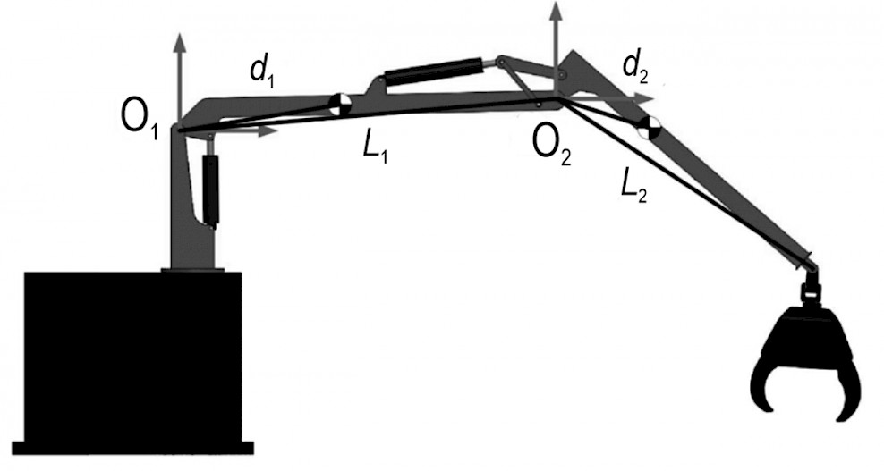
Fig. 4 Positions of centers of mass in a standard forwarder crane
The necessary calculations for designing and simulating a gravity compensated crane were also done within MATLAB. The fundamental formulations needed to perform these simulations and the design are presented below.
2.2 Methods
Our objective was to design a new counterweighted crane with a new set of parameters differing from those used for the standard crane (see Fig. 5). These parameters include masses and distances from the centers of mass to the corresponding pivot points.
In the area of mechatronics, mathematical optimization is the main method used for finding new optimal sets of parameters (Arakelian 2016). In our case, the optimization problem was solved in MATLAB, and it was formally postulated as follows: »Minimize the cylinder energy consumption by modifying the masses and center of masses of the crane booms, such that the weight of the standard crane is counterbalanced.«
The design of the new crane is shown in Fig. 5, where the new distances to the centers of mass are denoted as d1CW for the inner boom and d2CW for the outer boom. The values for the new masses are presented in section 4. Comparing the cranes of Fig. 4 and 5, it can be observed that Fig. 5 contains two additional counterweights included for the inner and outer boom. However, the lengths of the booms remain the same, as well as the placement of the cylinders. These characteristics are kept the same, so that both cranes are able to perform equal motions.
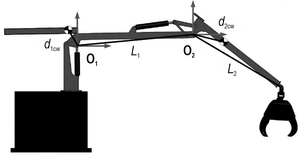
Fig. 5 Positions of centers of mass in a gravity compensated forwarder crane
The following are the summary of steps required to find an optimal design using mathematical optimization through software:
Þ define the performance criterion in terms of energy consumption
Þ perform iterative simulations of the crane modifying masses, inertias and positions of the centers of mass
Þ for each simulation, compute the cylinder energy consumption
Þ if the design achieves minimum energy or the maximum number of iterations is reached, terminate the process; otherwise, return to step 2.
If the optimization goal is achieved, the resulting parameters should correspond to a new gravity compensated crane that minimizes the energy consumption for the specified motions. A CAD model of the new crane with the final parameters was then developed. All the analytical tools required to perform these steps are presented below.
2.2.1 Performance Criterion
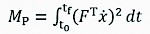
Our GC analysis started by defining a performance criterion for the optimization problem, i.e., a mathematical equation of what the GC design is attempting to achieve. For this particular case, GC was used to minimize the energy consumed by the cylinders when moving the crane. A parameter that quantifies the amount of energy transferred by a hydraulic cylinder during motion is mechanical power. It is important to recall that optimizing mechanical power correlates to fuel savings (Rakha et al. 2011).
Using concepts of classical mechanics, the method to compute the performance criterion based on mechanical power is by using the formulation (Manring 2005, Spong et al. 2006)
 (1)
(1)
Where:
Fare the cylinder forces and ̇ is the vector of cylinder velocities while delivering those forces.
Mechanical power is calculated for a finite time motion that starts at time t0 and ends at time tf.
2.2.2 Dynamics Modeling
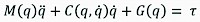
Computation of the performance criterion described by Eq. (1) requires data on forces and velocities. This data set was obtained from simulation results, where the simulation was performed according to crane dynamics. According to classical mechanics, the equation representing the dynamics of a mechanical system is explicitly defined by the generalized Euler-Lagrange formulation (Spong et al. 2006):
 (2)
(2)
Where:
position, velocities and accelerations of the joints
M(q) influence of the masses and inertias
C( ) and (Gq) effects of Coriolis and gravity
torques required at the joints to produce motion.
For interested readers, the complete formulation for a two-link robot using Eq. (2) can be found in (Spong et al. 2006).
It is important to note that Eq. (2) is a generalized expression that can be used similarly for a crane with or without gravity compensation. When performing simulations, the difference between these two cases was done by changing the parameters for the masses, inertias and the distances to the center of masses. Therefore, simulating these two cases was only a matter of modifying such parameters.
Eq. (2) was used to calculate the joint torques required to achieve the desired motion. The terms on the left-hand side of Eq. (2) are mathematical expressions that can be calculated once a desired trajectory has been specified and the values for masses, inertias and lengths are known. Specifying a desired trajectory means that the values for positions , velocities , and accelerations are explicitly given.
2.2.3 Relation Between Cylinder Forces and Joint Torques
It is important to remark that in Eq. (2), represents the angular torques exerted at the joints and not the cylinder forces. To relate these torques to cylinder forces, it was necessary to find the geometrical relationship between the joint angular position q with the cylinder piston displacement x. This geometrical relationship can be formulated as:
 (3)
(3)
Where:
x = [x1, x2] denotes the vector of piston displacements for the main and outer boom cylinders, respectively
q = [q1, q2] denotes the vector for the angular position of the main and outer booms, respectively.
According to classical mechanics, the relation torques to cylinder forces is given by (Spong et al. 2006):
 (4)
(4)
Where:
J is the Jacobian matrix of Eq. (3), and it can be computed as,
 (5)
(5)
Thus, once the angular torques for a specific motion were calculated using Eq. (2), the cylinder forces were calculated by,
 (6)
(6)
For interested readers, the complete formulation of f(q) can be found in (La Hera and Morales 2014).
2.2.4 Defining the Desired Motion
Fig. 6 shows the sketch of a motion where the crane is picking logs from the ground to the machine. As this is a standard task for these cranes, it was used as the desired motion profile in our optimization software.
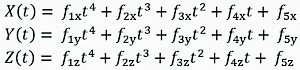
Initially, this motion was represented as a parabolic trajectory of the boom-tip in Cartesian Coordinates using polynomial functions, which is a standard approach to define motion in mechatronic systems (Spong et al. 2006). Our software used the following fourth order polynomial functions that define a parabolic path in space:
 (7)
(7)
Where:
= [1, 2, 3, 4, 5] and c = [x, y, z] represent the individual polynomial coefficients. The time progression of the motion is denoted by t. The variables [X(t), Y(t), Z(t)] denote the Cartesian Coordinates of the boom-tip, similar to what is sketched in Fig. 6.
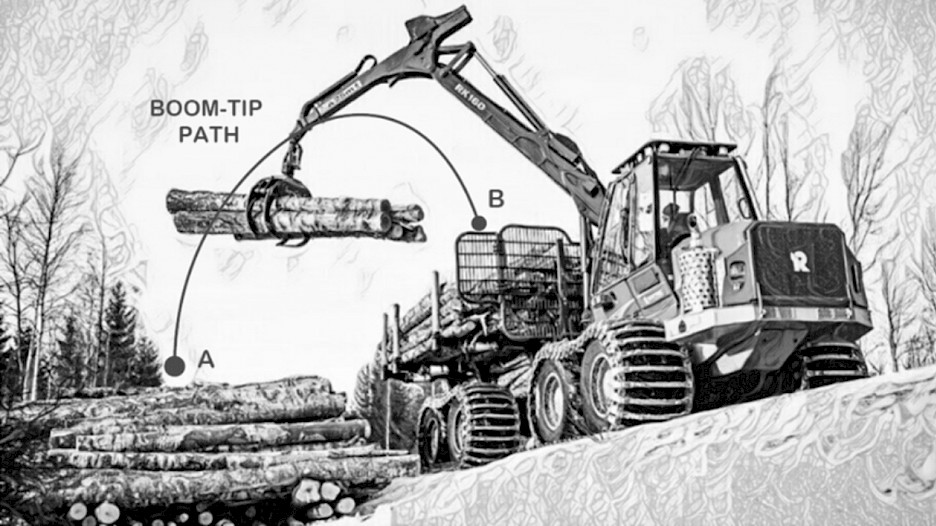
Fig. 6 Schematic representation of a standard forestry crane performing a parabolic-like motion
Secondly, in order to use the dynamics described by Eq. (2), the path described by Eq. (7) needs to be transformed into the individual joint motions giving information about position , velocity , and acceleration . To this end, our software used the crane inverse kinematic equations to compute the angular positions from specified boom-tip positions [X, Y, Z]. Kinematic equations of the crane are based on geometry and tell how the individual parts of the crane move (Spong et al. 2006). Mathematically, it can be formulated as:
 (8)
(8)
Where:
q are the individual joint positions
X = [X(t), Y(t), Z(t)] are specified in Eq. (7).
The function h(X) is the set of inverse kinematic equations. Thus, given a motion X = [X(t), Y(t), Z(t)], relation described by Eq. (8) was used to calculate . The remaining terms involving velocity and acceleration represent the first and second derivative of respectively. These variables were found by numerically differentiating within our MATLAB software. For interested readers, the complete formulation of inverse kinematics for a two-link robot using Eq. (8) can be found in (Spong et al. 2006).
2.2.5 Final Algorithm
Once all analytical functions have been defined, the design of a gravity compensated crane using mathematical optimization is achieved by algorithm 1.
Notice that in algorithm 1, the termination criterion depends on the settings of the optimization software. As it is not possible to make the energy consumption equal to zero, the program will run until it has reached a local minimum value that does not decrease upon further iterations or once it has reached the maximum number of iterations. At that point, the program terminates.
2.3 Performance Verification
In order to verify the performance of our design method, two test scenarios were considered. The first case was to evaluate crane performance only, a test that resembles a scenario in which the vehicle on which the crane is mounted is static, and the crane is the only one performing motion. The second test was performed considering also the transportation work, in a scenario where the vehicle is moving from an initial point to a final point to collect logs inside the forest. In this case, the mechanical power of the machine (vehicle and crane) is taken into account.
In both cases, the procedure consisted of simulating the crane with and without gravity compensation when doing identical work under identical conditions. Simulation results were used to perform calculations of energy consumption using Eq. (1), enabling a quantitative comparison between the standard crane and the gravity compensated crane.
Algorithm 1: Final algorithm for designing a gravity compensated crane
Result: An optimal set of parameters for masses and distances to center of masses
Data:
(1) Define a parabolic Cartesian trajectory according to Eq. (7).
(2) Calculate the joint trajectories according to Eq. (8).
(3) Initialize the values for the masses and distance to the center of masses according to the standard crane.
while termination criterion is not satisfied do as follows
(1) Calculate the joint torques according to Eq. (2).
(2) Calculate cylinder forces according to Eq. (6).
(3) Calculate energy according to Eq. (1).
if termination criterion is not satisfied then
Create a new set of values for masses and center of masses,
or else
Exit the values for masses and center of masses.
end
end
2.3.1 Energy Performance with a Static Vehicle
The first test compared energy consumption when both cranes performed similar motions. Since our design method focused only on the design of the crane, this test was done to evaluate the energy savings achievable by optimizing the performance criterion described by Eq. (1). Tests were done under the following constraints:
Þ the crane has no logs in the grapple, because the inertial parameters (mass and inertia) of the log will not considerably change the energy performance comparison if both cranes perform similar motions. This is because energy calculation including the inertial parameters of logs only slightly alters the performance criterion, which is identical for both cranes
Þ the crane is tested at different speeds, taking 20, 30 and 40 seconds to traverse the path described by Eq. (7). The lower and upper limits of this range represent the fastest and slowest motions that our crane can perform given the velocity limits of the cylinders.
2.3.2 Energy Performance with a Moving Machine
The design procedure for the gravity compensated crane is purely based on the loading task when considering its mechanical parameters. However, it is important to also asses overall machine performance when considering the gravity compensated crane in order to understand the overall benefits or drawbacks of this design methodology. Therefore, the second case assumes that both cranes are individually mounted on a forwarder moving over flat forest terrain. The scenario assumes that the machine has to perform the following tasks:
Þ initially, the machine travels empty from an initial point Pi to a final point Pf, where the crane loads logs into the log-bunk until it is fully loaded. During the loading period, the vehicle is static.
Þ finally, the machine travels fully loaded back from the final point Pf, to the initial point Pi, where the crane unloads logs to the landing area. During the unloading period, the vehicle is static.
Þ to understand how the traveling distance affects energy consumption, additional simulations were performed in which the distance between points Pi and Pf was increased progressively from 50 m to 1 km.
As our performance criterion only considers the energy consumption of the crane, it was necessary to also compute the mechanical power of the machine when the vehicle is moving and the crane is motionless. This was formulated as follows:
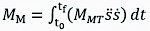 (9)
(9)
Where:
MMT the total mass of the vehicle and crane
vehicle velocity
vehicle acceleration.
Thus, for this particular test, the complete expression to quantify energy consumptions is given by:
 (10)
(10)
Where:
mechanical power required to drive the machine from point Pi to point Pf
mechanical power required for the crane work at point Pf (loading task).
mechanical power required to drive the machine from point Pf to point Pi
mechanical power required for the crane work at point Pi (unloading task).
In order to add additional constraints for simulation studies, our work used data observed in the work of (Manner et al. 2016). In particular, the following constraints were applied to ensure that the simulated system had properties consistent with the requirement of Scandinavian forestry:
Þ the maximum weight of a fully loaded machine is 40.8 tons, where 21.8 tons is the total weight of the vehicle with a standard crane
Þ driving speed when the machine is empty (without logs) is 55 m/min.
Þ driving speed when the machine is fully loaded (with logs) is 36.7 m/min.
Under all these considerations, the purpose is to demonstrate the energy savings achieved with GC subject to these constraints. However, we would like to emphasize that the results of this evaluation should be considered only as a rough approximation of energy savings, because the work of a real forest machine is more complex and difficult to be simulated.
3. Results
The results of our study are presented in three separate sections. The first presents the main results obtained using Algorithm 1. The second presents the performance verification described in section 2.3.1. The third presents the performance verification using the whole machine, as described in section 2.3.2.
3.1 Design Results
As explained in section 2, the main design consideration was to minimize energy consumption by optimizing the performance criterion of Eq. (1). Referring to Fig. 4, the mechanical parameters of the standard crane are presented in the second column of Table 1. Consequently, referring to Fig. 5, software results of Algorithm 1 are presented in the third column of Table 1. To find these results, our software algorithm running under MATLAB took 50 iterations to complete. Iterations were finalized in approximately 3 hours, which is common for these design cases mainly due to the complexity of the software used for all the simulations and calculations.
Table 1 Physical properties of cranes
|
Property |
Standard crane |
Crane with counterweights |
|
d1|d1 cw, m |
1.2987 |
0.3913 |
|
D2|d2 cw, m |
0.9921 |
0.9858 |
|
m1, kg |
332.54 |
650.88 |
|
m2, kg |
226.50 |
228.01 |
As shown in Table 1, when compared to the standard crane, the gravity compensated crane presents the following characteristics:
Þ the distance to the center of mass for the inner boom reduced by nearly 70%, placing the weight of the inner boom closer to the main cylinder. However, the position of the center of mass of the outer boom was barely changed
Þ to counterweight the standard crane, the new design uses nearly 318 kg of extra mass placed on the inner boom. It uses only 2 kg extra mass for the outer boom, which is almost negligible. Adding the counterweight required by the results of our algorithm increased the crane total mass by 57%.
3.2 Energy Performance Results with a Static Vehicle
For this test, the main goal was to compare the energy performance of the standard crane and the gravity compensated crane when both perform similar motions. Fig. 7 shows the parabolic trajectory used for testing. In the trajectory for both cranes, the Cartesian coordinates of the grapple starting point were [3 m, 0 m, –2 m], while the Cartesian coordinates for the ending point were [0.50 m, 3.35 m, 0.07 m]. As explained earlier, the time allocation t in polynomials of Eq. (7) is defined to accomplish the motion in 20, 30 and 40 seconds, testing both cranes at different speeds. The additional polynomial coefficients in Eq. (7) for this trajectory are:
(11)
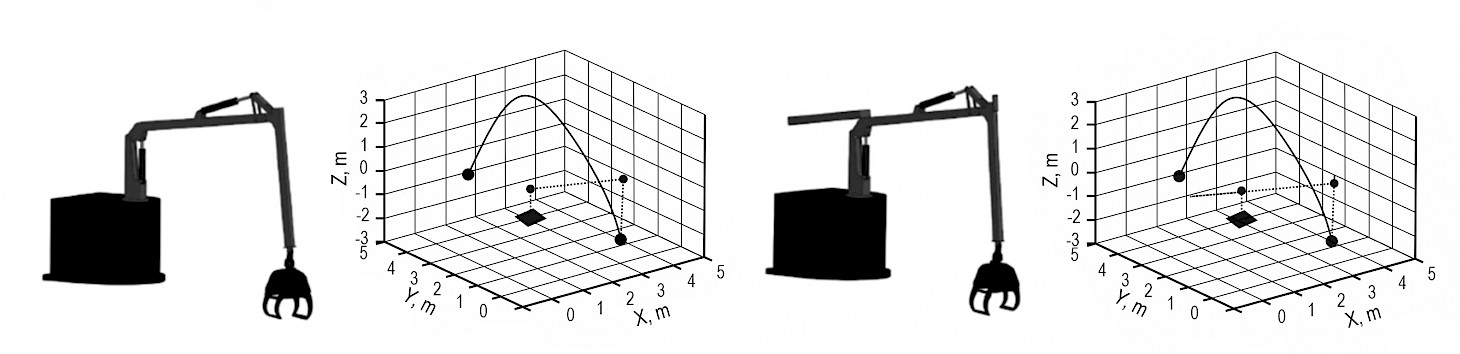
Fig. 7 Schematic representation of test trajectory. For both cases, cranes were placed at the initial position [3 m, 0 m, –2 m]
Under all these considerations, Fig. 8 shows the results of the mechanical power calculated for each crane using Eq. (1). In addition, the total mechanical power for both cranes is presented in Table 2. Observing the last column of Table 2, it can be concluded that energy savings with our gravity compensated crane using counterweights was on average 27%.
Table 2 Energy consumption (Mechanical Power) for both cranes at different speeds
|
Time, s |
Standard crane, MW |
Crane with cw, MW |
Relative difference, % |
|
20 |
16.938 |
12.377 |
26.92 |
|
30 |
11.059 |
8.0567 |
27.14 |
|
40 |
8.2154 |
5.9771 |
27.24 |
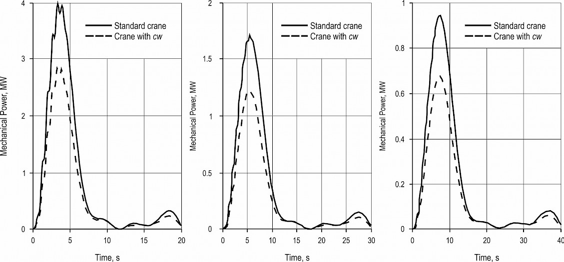
Fig. 8 Mechanical power (energy consumption) for both cranes at different speeds (i.e. different allowed movement durations – note different scales on x-axes)
3.3 Results of Energy Performance with a Moving Vehicle
As mentioned in section 2.3.2, the maximum weight of a fully loaded machine is 40.8 tons. Considering that the gravity compensated crane increased the weight of the machine by approximately 1.4%, the maximum loads that both machines can carry were:
Þ 19 tons of logs for the standard crane (approximately 21.1 m3)
Þ 18.68 tons of logs for the gravity compensated crane (approximately 20.75 m3).
Fig. 9 shows the energy savings as a function of the distance traveled. Therefore, the test concluded that the overall energy savings obtained by using GC with counterweights depends on the distance traveled. For distances below 500 meters, the energy saving is above 5%, while for distances above 500 meters, the energy saving is below 5%.
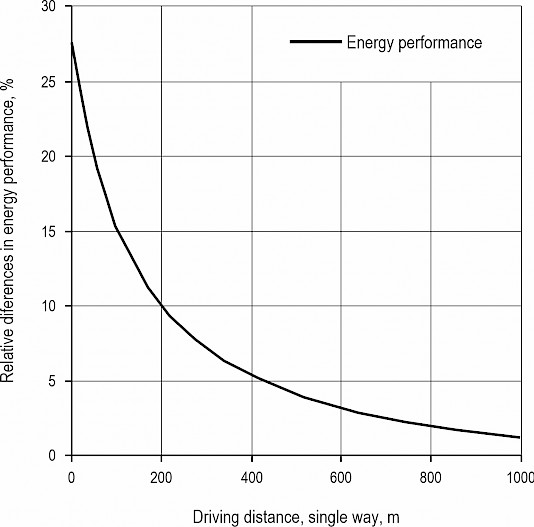
Fig. 9 Relative differences between forwarder work performances with a crane with GC and a standard crane. A positive relative difference indicates that the crane with GC has a lower energy consumption
4. Discussion
4.1 Discussion about Results
Gravity compensation is widely used to design energy efficient mechanical systems, but its application to forestry cranes has not been previously reported, to the best of our knowledge. The objective of this study was to introduce GC and determine whether it can substantially reduce energy consumption to be considered as an alternative design method for forestry machines. To this end, we first investigated the concept of gravity compensation by counterweights.
As demonstrated in our work, using gravity compensation requires a complex design procedure including fundamental analysis of both dynamics and kinematics, as well as computational design based on mathematical optimization and simulation. Energy performance verification of our gravity compensated crane demonstrated that this technology can be instrumental in improving energy efficiency by 27%, at the cost of increasing the crane mass by 57%. Nevertheless, it is possible to increase energy efficiency more substantially by performing modifications as explained below.
This study has several strengths. First, we developed a generalized methodology for applying gravity compensation using a relatively simple example of a crane with only two booms. For other cases, one could use a similar optimization procedure with slight adjustments on the main dynamics and kinematics equations. Second, although our crane did not have the standard telescopic link in the outer boom, our results indicate that very little mass (less than 1%) is needed to counterweight the outer boom. The dynamic influence of a telescopic link would not change this result so dramatically. Third, we showed energy savings not only for the crane under our design parameters, but also when the crane is mounted on a vehicle performing a semi-real work task. However, we point out that the results presented here should not be generalized too far because tasks inside the forest are more complex than our test example. Nevertheless, we are confident that energy savings can be achieved in general, as there exist many other industrial examples demonstrating this fact (Takesue 2011). In order to keep the total mass of the loaded machine, the used concept of GC required a payload reduction of 332 kg, which corresponds to approximately 0.35 m3, and thereby a reduction in payload volume of 1.6%. In theory, this would result in a reduced productivity, implying a trade-off between energy savings and productivity. If the optimization problem is stated to minimize costs, the outcome of this trade-off will depend on the relationship between fuel costs and the payment per forwarded m3. However, it can be argued that such a small payload reduction would never be effectuated in practice, and that this payload reduction might not be needed if other gravity compensation approaches are used. Therefore, this trade-off was not explored further in this paper.
Despite the benefits of our approach, some limitations of our study should be addressed. First, the design of our gravity compensated crane relies on an optimization algorithm that takes several hours to complete. During this project, we found many design cases achieving energy reductions of up to 70% at the cost of increasing crane mass by over 90%. The example in this article was chosen due to its simplicity and conservative results, but it could be certainly possible to find solutions that can save energy in much higher amounts by exploring different sets of initial conditions and modifying the constraints of the optimization problem. Nevertheless, this falls outside the scope of the present study, because a study of this kind would require access to a multi-core computer (a.k.a. super computer), which we do not currently have. Second, as the principle of counterweight implies to balance a system by adding extra weight, this concept may be undesirable for forestry industry, due to the nature of the work performed by forestry cranes. However, there are two methods that can directly tackle this problem. Initially, one could consider designing a counterweight with a constraint in the problem, where the total mass of the crane does not increase. As this would result in a lighter crane, it would be necessary to consider additional constraints, such as, stress analysis to verify if such a crane has the ability to sustain the expected load without suffering deformation. Such an analysis falls outside the scope of the present study, but it could be simply added to our optimization algorithm. A second alternative, and perhaps the most relevant case, would be to consider passive gravity compensation (see the right Fig. 2), where additional devices would help producing forces to balance the dynamics of the crane. These devices (such as springs and dampers) are often light and widely available. Cranes with gravity compensation by considering passive elements would not have any extra mass, but performing such a design falls outside the scope of this study, because it would imply to change the whole design philosophy, as well as the design algorithms. However, it is important to recall that industrial design of gravity compensated systems often uses a combination of all these methods in the design of a single system (Lu et al. 2011). For instance, most mechanical manipulators in the automation industry use a combination of counterweights and passive gravity compensation (Arakelian 2016).
4.2 General Discussion
Energy consumption is often the major contributor to overall costs when operating industrial machinery. On average, energy consumption accounts for between 20% and 30% of total equipment operating costs. In energy-intensive hydraulic applications, the contribution of energy costs is often greater. As energy management is becoming a major issue for industry, manufacturing reliable machines is no longer enough. Therefore, producing highly efficient and reliable machines with low carbon footprint is becoming a priority for machine manufacturers, and technologies designed to accommodate these goals have recently been adopted in forestry.
Although being a relatively simple example, our present study here opens a door to a new design philosophy for forestry cranes. Gravity compensated cranes have many inherited properties that we have not addressed to focus on the design methodology. However, some of important benefits of gravity compensation (which also present opportunities to improve on the showcased here) include:
Þ Maintenance. Gravity compensated systems often require less maintenance than their counterparts because the stress placed on the actuators and joints is greatly reduced. The life expectancy of a gravity compensated system is thus longer. These characteristics represent financial benefits of GC
Þ Automation. One of the main problems with standard cranes is the residual oscillations due to their flexibility. Automation under this form of dynamics represents a significant challenge, and partly explains why there has been a lack of automation in forestry despite years of research in this area. However, research on robotics has shown that gravity compensated systems are simpler to automate because gravity compensation inherently tends to reduce oscillations. This is one of the main reasons why most industrial robotics is based on gravity compensated robot manipulators, as they improve both accuracy and safety
Þ Smart Motion Software. Our design method mainly considers the mechanical properties of the crane, in order to develop a gravity compensated version. However, robotics research has shown that energy efficient motions can reduce energy consumption by up to 25%. Combining our design approach with smart motion software could thus deliver greater energy savings than those presented here. Interested readers can find more information about this topic in (Dong et al. 2020)
Þ Modifying the overall crane design. Since their first appearance in forestry machines, the design of forestry cranes has largely remained unchanged. Over the years, manufacturers have increased the size and strength of these cranes, but not the design philosophy. However, modifying the crane architecture could result in crane designs with better inherited properties. Similar steps have been observed in the robotics industry, where robot manipulators have passed through design improvements over the years. Combining new crane designs and gravity compensation offers the potential of high energy savings with lighter cranes that are safer and easier to control
Þ Electrification. As is the case for most industries, developing low footprint forestry machines will require several years of redesign work. Current forestry machines are quite heavy, difficult to operate, and cause environmental damage (Mederski et al. 2020). With current design methods, it is infeasible to move away from hydraulic systems, which require large and heavy pumps, oil tanks, and engines to operate. As a matter of comparison, the area of robotics show cases of fully electric manipulators capable of lifting loads heavier than those encountered in forestry. The introduction of gravity compensation offers an opportunity to start transitioning from hydraulics to purely electrical systems, at least in cranes. In addition, electrical systems are inherently simpler to automate than hydraulic ones, and increasing automation is a long term objective in the forest industry. Thus, we can expect that electrically driven cranes, in contrast to hydraulically driven cranes, are a better venue to achieve such goals.
5. Conclusion
In conclusion, this article has provided an initial demonstration of how gravity compensation could be applied in the forest industry to develop a new generation of highly energy efficient forestry cranes. The results obtained are quite conservative, but show that this technology can deliver energy savings of at least 27% during crane work. As there are many design philosophies that can be adopted in combination with gravity compensation, our results cannot address all possible scenarios. Therefore, design methods using gravity compensation alone or in combination with other technologies represent an important area for further research in the effort to develop forestry machines with smaller carbon footprints.
Acknowledgments
This study was partly financed by the Swedish Energy Agency (project HAFSBiT, 48003-1), the Swedish Foundation for Strategic Environmental Research MISTRA (program Mistra Digital Forest), the Kempe Foundations (projects JCK-1713 and JCK-2120), the Royal Swedish Agricultural Academy (project GFS2020-0022) and the Swedish Cluster of Forest Technology.
6. References
Arakelian, V., 2016: Gravity compensation in robotics. Advanced Robotics 30(2): 79–96. https://doi.org/10.1080/01691864.2015.1090334
Boisclair, J., Richard, P., Laliberte, T., Gosselin, C., 2016: Gravity compensation of robotic manipulators using cylindrical halbach arrays. IEEE/ASME Transactions on Mechatronics 22(1): 457–464. https://doi.org/10.1109/TMECH.2016.2614386
Briot, S., Arakelian, V., 2015: A new energy-free gravity-compensation adaptive system for balancing of 4-dof robot manipulators with variable payloads. The 14th IFToMM World Congress, Taipei, Taiwan, October 25–30. https://doi.org/10.6567/IFToMM.14TH.WC.OS13.038
Dong, X., Mendoza-Trejo, O., Ortiz Morales, D., Lindroos, L., La Hera, P., 2020: Simulation-based comparison between two crane-bunk systems for loading work when considering energy-optimal motion planning. International Journal of Forest Engineering 31(1): 70–77. https://doi.org/10.1080/14942119.2019.1653027
EATON, 2019: https://www.eaton.com/us/en-us/catalog/valves/cmaadvanced-mobile-valves.resources.html
Gerasimov, Y.Y., Siounev, V.S. 2000: Forest machinery crane compound scheme synthesis: Optimization of hydraulic cylinder operating mechanism. International Journal of Forest Engineering 11(1): 73–79. https://doi.org/10.1080/08435243.2000.10702746
Gosselin, C., 2008: Gravity compensation, static balancing and dynamic balancing of parallel mechanisms. In: Smart devices and machines for advanced manufacturing. London: Springer, 27–48.
Häggström, C., Lindroos, O., 2016: Human, technology, organization and environment – a human factors perspective on performance in forest harvesting. International Journal of Forest Engineering 27(2): 67–78. https://doi.org/10.1080/14942119.2016.1170495
John Deere, 2012: Smooth boom control. http://www.deere.co.uk/
Kalmaria, J., Backman, J., Visala, A., 2017: Coordinated motion of a hydraulic forestry crane and a vehicle using nonlinear model predictive control. Computers and Electronics in Agriculture 133: 119–127. https://doi.org/10.1016/j.compag.2016.12.013
Komatsu Forest AB., 2017: Komatsu smartflow – new hydraulic system for forwarder. https://www.forestry.com/editorial/equipments/komatsu-smartflow-hydraulicsystem-forwarder/
La Hera, P., Ortiz Morales, D., 2014: Non-linear dynamics modelling description for simulating the behavior of forestry cranes. International Journal of Modelling, Identification and Control 21(2): 125–138. https://doi.org/10.1504/ijmic.2014.060006
La Hera, P., Ortiz Morales, D., Mendoza-Trejo, O., 2021. A study case of Dynamic Motion Primitives as a motion planning method to automate the work of forestry cranes. Computers and Electronics in Agriculture 183: 106037. https://doi.org/10.1016/j.compag.2021.106037
Lindroos, O., Bergström, D., Johansson, P., Nordfjell, T., 2008: Cutting corners with a new crane concept. International Journal of Forest Engineering 19(2): 21–28. https://doi.org/10.1080/14942119.2008.10702564
Lindroos, O., Ringdahl, O., La Hera, P., Hohnloser, P., Hellström, T., 2015: Estimating the Position of the Harvester Head – a Key Step towards the Precision Forestry of the Future? Croatian Journal of Forest Engineering 36(2): 147–164.
Lu, Q., Ortega, C., Ma, O., 2011: Passive gravity compensation mechanisms: technologies and applications. Recent Patents on Engineering 5(1): 32–44. https://doi.org/10.2174/1872212111105010032
Lundbäck, M., Häggström, C., Nordfjell, T., 2021. Worldwide trends in methods for harvesting and extracting industrial roundwood. International Journal of Forest Engineering 32(3): 202–215. https://doi.org/10.1080/14942119.2021.1906617
Malinen, J., Taskinen, J., Tolppa, T., 2018: Productivity of Cut-to-Length Harvesting by Operators’ Age and Experience. Croatian Journal of Forest Engineering 39(1): 15–22.
Manner, J., Mörk, A., Englund, M., 2019: Comparing forwarder boom-control systems based on an automatically recorded follow-up dataset. Silva Fennica 53(2): 10161. https://doi.org/10.14214/sf.10161
Manner, J., Nordfjell, T., Lindroos, O., 2016: Automatic load level follow-up of forwarders’ fuel and time consumption. International Journal of Forest Engineering 27(3): 151–160. https://doi.org/10.1080/14942119.2016.1231484
Manring, N., 2005: Hydraulic control systems (First ed.). New York, USA: John Wiley & Sons.
Mederski, P., Borz, S., Duka, A., Lazdiņš, 2020: Challenges in Forestry and Forest Engineering-Case Studies from Four Countries in East Europe. Croatian Journal of Forest Engineering 42(1): 1–28. https://doi.org/10.5552/crojfe.2021.838
Nurmi, J., Mattila, J., 2017: Global energy-optimal redundancy resolution of hydraulic manipulators: Experimental results for a forestry manipulator. Energies 10(5): 647. https://doi.org/10.3390/en10050647
Ortiz Morales, D., Westerberg, S., La Hera, P.X., Mettin, U., Freidovich, L., Shiriaev, A.S., 2014: Increasing the level of automation in the forestry logging process with crane trajectory planning and control. Journal of Field Robotics 31(3): 343–363. https://doi.org/10.1002/rob.21496
Pagnussat, M., Hauge, T., Lopes, E., Martins de Almeida, R., Naldony, A., 2020: Bimanual Motor Skill in Recruitment of Forest Harvest Machine Operators. Croatian Journal of Forest Engineering 41(1): 25–33. https://doi.org/10.5552/crojfe.2020.623
Rakha, H.A., Ahn, K., Moran, K., Saerens, B., Van den Bulck, E., 2011: Virginia tech comprehensive power-based fuel consumption model: model development and testing. Transportation Research Part D: Transport and Environment 16(7): 492–503. https://doi.org/10.1016/j.trd.2011.05.008
Riazi, S., Bengtsson, K., Wigström, O., Vidarsson, E., Lennartson, B., 2015: Energy optimization of multi-robot systems. In 2015 IEEE international conference on automation science and engineering (case): 1345–1350.
Riazi, S., Wigström, O., Bengtsson, K., Lennartson, B., 2017: Energy and peak power optimization of time-bounded robot trajectories. IEEE Transactions on Automation Science and Engineering 14(2): 646–657. https://doi.org/10.1109/TASE.2016.2641743
Spong, M., Hutchinson, S., Vidyasagar, M., 2006: Robot modeling and control. New Jersey: John Wiley and Sons.
Takesue, N., 2011: Gravity compensation mechanisms for energy-saving and safety. Journal of the Robotics Society of Japan 29(6): 508–511. https://doi.org/10.7210/jrsj.29.481
Technion, 2017: Crane control systems. https://technion.fi/crane-controlsystems/
The Mathworks, 1990: http://www.mathworks.com
Yamamoto, R., Hirakawa, A., Horikawa, O., 2010: Load balancer with automatic lifting force compensation. In Abcm symposium series in mechatronics 4: 580–589.
© 2022 by the authors. Submitted for possible open access publication under the
terms and conditions of the Creative Commons Attribution (CC BY) license (http://creativecommons.org/licenses/by/4.0/).
Authors’ addresses:
Omar Mendoza-Trejo, PhD *
e-mail: omar.mendoza.trejo@slu.se
Ola Lindroos, PhD
e-mail: ola.lindroos@slu.se
Pedro La Hera, PhD
e-mail: Xavier.lahera@slu.se
Swedish University of Agricultural Sciences
Department of Forests Biomaterials and Technology
Skogsmarksgränd 17
90183, Umeå
SWEDEN
Arturo D. López Rojas, MSc
e-mail: desaix.rojas@cinvestav.mx
Carlos A. Cruz-Villar, PhD
e-mail: cacruz@cinvestav.mx
Center for Research and Advanced Studies of the National Polytechnic Institute (CINVESTAV)
Electrical Engineering Department
Mechatronics Section
Av. IPN, 2508, San Pedro Zacatenco
07360, Mexico City
MEXICO
Daniel Ortiz Morales, PhD
e-mail: daniel.morales@cranab.se
CRANAB AB
Karlsgårdsvägen 56
92232, Vindeln
SWEDEN
* Corresponding author
Received: December 11, 2020
Accepted: January 20, 2022
Original scientific paper