Development and Evaluation of a Felling Head for a Light Forest Crawler
doi: 10.5552/crojfe.2024.2048
volume: 45, issue:
pp: 15
- Author(s):
-
- Knobloch Christian
- Erler Jörn
- Pfanzelt Paul
- Richter Lars
- Article category:
- Original scientific paper
- Keywords:
- felling head, machine development, mechanization of motor-manual harvesting, accident avoidance, automatization of tree felling process
Abstract
HTML
With motor-manual wood harvesting (by a forest worker with a chainsaw) fatal accidents happen every year when the tree is felled or when parts of the crown fall down. The alternative is to fell trees mechanically using a timber harvester head, which, however, must be brought up to the trees in the forest by means of its crane. With the usual crane reach of 10 m, the harvester needs a system of parallel strip roads with a spacing of 20 m. Furthermore, the harvester needs a dead weight of around 20 tons that compacts the soil. Both consequences increasingly evoke critics. The requirement to fell trees mechanically and to enlarge the distance between the strip roads calls for a solution to fell trees with a small, light machine that can apply its felling tool to the tree in close proximity. Together Pfanzelt Maschinenbau GmbH and the Professorship for Forest Technology of Technische Universität Dresden have run a project for developing a compact, new type of felling head, which is attached to the existing forest crawler »Moritz FR70/75« by means of a short manipulation arm. This head imitates the felling technique, which is applied by a forest worker, in a mechanical way with a high grade of automatization. Even though this machine works with higher system costs, it is significantly faster and more precise than the motor-manual version. The functional principle of the felling head was developed, patented, conceptualized and optimized with the help of prototypes and individual tests at the TU Dresden, Professorship for Forest Technology. After that, it was completely designed, manufactured and automated in terms of control technology by the Pfanzelt company. More than 100 conifers with a felling diameter of up to 50 cm were felled safely and without any problems with the prototype. The possible integration into harvesting processes as well as the effects on the use in the forest stands were analyzed in detail. The project has shown that it is possible to fell trees in a fully mechanized way without danger for the forest worker with a machine that weights roughly a tenth of the dead weight of a conventional harvester.
Development and Evaluation of a Felling Head for a Light Forest Crawler
Christian Knobloch, Jörn Erler, Paul Pfanzelt, Lars Richter
Abstract
With motor-manual wood harvesting (by a forest worker with a chainsaw) fatal accidents happen every year when the tree is felled or when parts of the crown fall down. The alternative is to fell trees mechanically using a timber harvester head, which, however, must be brought up to the trees in the forest by means of its crane. With the usual crane reach of 10 m, the harvester needs a system of parallel strip roads with a spacing of 20 m. Furthermore, the harvester needs a dead weight of around 20 tons that compacts the soil. Both consequences increasingly evoke critics. The requirement to fell trees mechanically and to enlarge the distance between the strip roads calls for a solution to fell trees with a small, light machine that can apply its felling tool to the tree in close proximity. Together Pfanzelt Maschinenbau GmbH and the Professorship for Forest Technology of Technische Universität Dresden have run a project for developing a compact, new type of felling head, which is attached to the existing forest crawler »Moritz FR70/75« by means of a short manipulation arm. This head imitates the felling technique, which is applied by a forest worker, in a mechanical way with a high grade of automatization. Even though this machine works with higher system costs, it is significantly faster and more precise than the motor-manual version. The functional principle of the felling head was developed, patented, conceptualized and optimized with the help of prototypes and individual tests at the TU Dresden, Professorship for Forest Technology. After that, it was completely designed, manufactured and automated in terms of control technology by the Pfanzelt company. More than 100 conifers with a felling diameter of up to 50 cm were felled safely and without any problems with the prototype. The possible integration into harvesting processes as well as the effects on the use in the forest stands were analyzed in detail. The project has shown that it is possible to fell trees in a fully mechanized way without danger for the forest worker with a machine that weights roughly a tenth of the dead weight of a conventional harvester.
Keywords: felling head, machine development, mechanization of motor-manual harvesting, accident avoidance, automatization of tree felling process
1. Introduction
As a standard in Central Europe in traffcable terrain, trees are felled and processed by a harvester. This wheeled machine, which weighs around 20 tons, has a crane with a standard outreach of 10 m and a harvester head at its end, which has a weight of 600 to 1000 kg (Sanktjohannser 2019). This universal tool can fix itself to a tree, cut it from the stock with the help of a hydraulically driven chainsaw (felling saw) and manipulate it with the crane in a way that the felling direction (away from the harvester) is fixed. Furthermore, the unit is able to delimb, measure and buck the tree. This requires the forces of a strong crane and the inertia of the base vehicle. For felling, the tools must be aligned parallel to the trunk. Furthermore, it must be able to lift the tree and it needs a tilting device and a rotator in order to grip the tree from the side.
While the harvester is compacting the forest soil, its action is limited to defined strip roads, which have a distance of 20 m to reach all stems with its 10 m long crane. Due to physical limits, longer crane ranges of up to 15 m are possible, but they greatly increase the weight of the harvester in order to provide the necessary counterweight.
As harvester heads are engineered in Scandinavia and optimized for softwood trees, their utilization in hardwoods, which often occurs in Central Europe, is limited (Mederski et al. 2022). For felling bigger hardwood trees, the dangerous motor-manual felling is the only option (Labelle et. al 2018).
For a couple of forest owners and forest organizations, the narrow distance of the strip roads combined with the large masses of the machines are not acceptable (FSC 2018). The forest managers try to widen the distances between the strip roads, while the forest land between the strip roads is divided into two zones. In the so-called crane zone, the timber harvester continues its work unchanged; but in the so-called intermediate zone, which cannot be reached by the harvester's crane, the trees are felled in a way that they fall into the crane zone and can there be processed in the second pass by the harvester. This felling operation in the intermediate zone is carried out by a forest worker with his motor saw manually. If this sequence is followed carefully, experiences indicate that the damage to the product and to the forest stands are very small and the additional costs vary in a small and acceptable range. But the disadvantage of this solution is that the forest worker has to work next to the falling trunk under its crown. Here he is endangered by splintering wood and, above all, falling crown parts and branches, which can come from the tree to be felled as well as from the neighboring trees. With motor-manual wood harvesting, fatal accidents happen every year (Michels 2017). Particularly in Germany, these risks increase, as more old and rotten trees are said to remain in the forest as a result of the greater compliance with nature conservation requirements (German Federal Ministry of Food, Agriculture and Consumer Protection 2011). In addition, longer periods of drought (Pfenninger et al. 2021) or tree diseases can lead to increasing instability of the trees and thus cause the trees to behave unexpectedly during the felling process, which in some cases exposes the forest workers to an unacceptable risk. Thus, the forest owner must decide between soil protection (wider distances of strip roads) and safety of the forest workers (full mechanization).
2. State of Knowledge
With regard to the crawler technology already in use, the literature research has shown that crawlers are actually used in the forest and that they are currently subject to new developments (Badgujar et al. 2023).
However, almost all attachments for crawlers are focused on soil cultivation or skidding. There are only two known forest crawlers that have a loading arm. The first crawler, PTH Hyomag E331, has a loading arm but is a concept study not currently available on the market (Friedrich 2019). The second crawler named »flailbot« is a device that can mainly be used to lift loads. The vehicle seems to be already established on the market (Bomford Turner Limited 2019).
A New Zealand patent describes a solution, which is near to the objective of the project: NZ717787 – Tree Felling Attachment (Scott 2014). The fully mechanized copy of the motor-manual felling technique is described as follows: With the help of a robot arm, which aligns itself with the tree axis with the help of sensors, the notch and the felling cut is carried out. Gripping arms press the rigid back of the unit firmly against the tree. A hydraulic arm, which is in contact with the ground, pushes the tree over the center of gravity after the felling cut, so that it falls in the specified direction (Scott 2014). The patent sketch can be seen in Fig. 1.
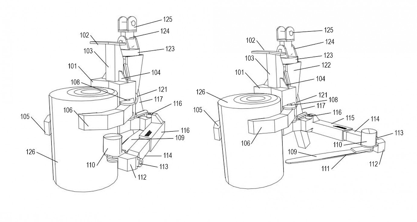
Fig. 1 Patent sketch as a counterposition of the concept design (Scott 2014)
3. Machine Design Conceptualization
Together Pfanzelt Maschinenbau GmbH and the Professorship for Forest Technology of Technische Universität Dresden have run a project, which was financed by ZIM (central innovation program for medium-sized companies) under project number 16KN079421. Herewith a compact, new type of felling head was developed, which is attached to the existing forest crawler »Moritz FR70/75« (Pfanzelt 2022) by means of a short manipulation arm. This head imitates the felling technique, which is applied by a forest worker, in a mechanical way with a high grade of automatization.
Our goal is to fell the trees in the intermediate zone by a machine that can work in a remote manner partially automatically and is light enough not cause any compaction to the soil. Such machines are available on the market in the form of crawlers, which are designed for skidding logs (Berendt et al. 2018). So far, there has been no machine on the market that is able to fell trees (above a breast height diameter of 20 cm) mechanically and partially automatically.
Taking over the working method of a harvester is also not possible because the harvester has to grab the tree and put it on the ground, using its own mass as a counterweight. This principle and the requirement for a low net weight are mutually exclusive. Therefore, a very new solution had to be developed. It was decided that the independent felling unit should only carry out the most dangerous felling process, nothing else. Since it should get by without a crane and inertia, it is subject to the same restrictions that the forest worker is exposed to when he is felling a tree motor-manually. Therefore, it was decided that the machine should mechanically imitate the conventional felling technique used by the forest worker.
Our felling unit shows a different principle of operation. It aligns the tree axis with the tools in a way that the entire unit automatically adjusts itself to the tree axis. The cuts are made by hydraulically operated chainsaws, while the lifting is carried out with the aid of a hydraulic cone drill. The machine concept can be seen in Fig. 2 and Fig. 3.
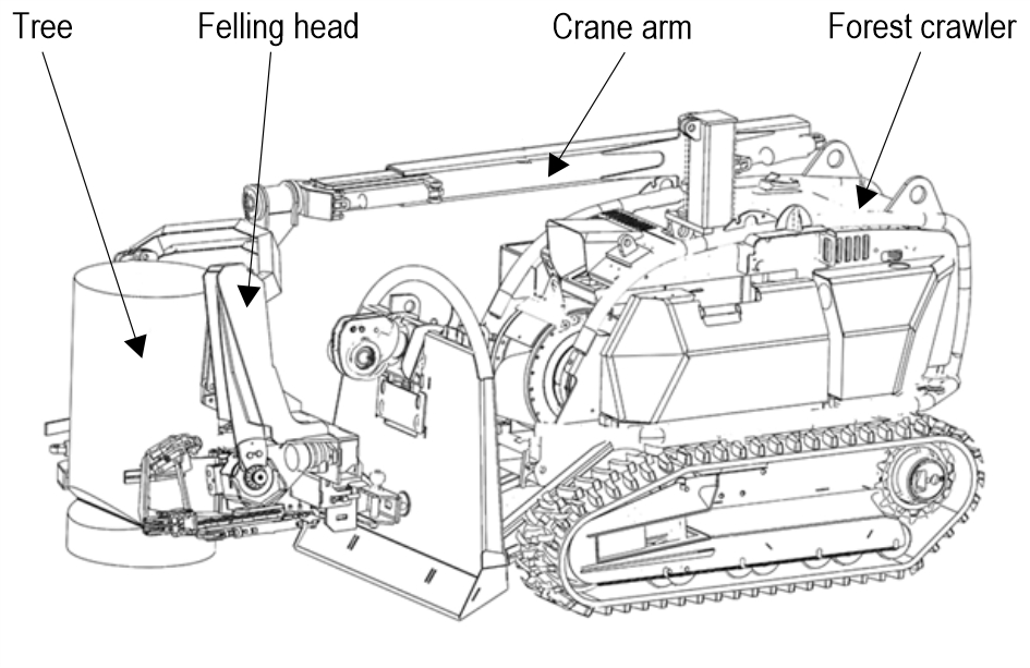
Fig. 2 Total machine concept
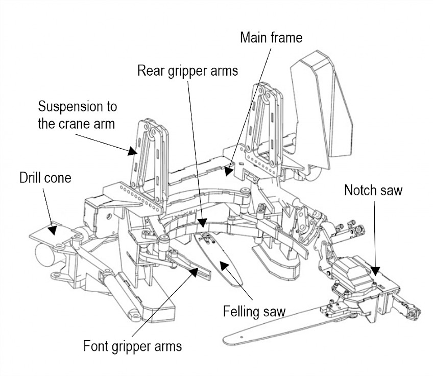
Fig. 3 Felling head of the machine concept
The felling unit hangs pendularly on a manipulation crane arm, which is attached to the crawler, with two degrees of freedom (Fig. 3, B). The cable winch and the three-point hydraulic system of the crawler can be used independently, for example to stabilize the machine.
The functions are as follows:
the crane arm enables the aggregate to be roughly positioned on the tree and the direction of felling to be determined
gripper arms carry out the fine alignment of the unit to the trunk axis as well as the alignment of all felling tools and their adaption to the diameter (Fig. 3, C and D)
the notch saw moves out of its housing and is folded in front of the tree (Fig. 3, G)
the notch saw makes the notch cut in two steps; the notch falls out
the notch saw is folded back; the saw bar moves into its housing
a separate felling saw (Fig. 3, E) moves from one saw box to the opposite one and performs the felling cut. In the middle position, it stops briefly until the mechanical drill cone, which is stowed at the rear (Fig. 3, A), pushes into the saw gap and holds it open
the gripper arms open, the tree stands stable only on the hinge and drill wedge
by turning the drill wedge, the tree is lifted above its center of gravity and falls into the desired direction
as soon as the tree falls, the machine automatically moves into the backward position.
The tool guides ultimately require 5 degrees of freedom, the tools require 3 individual drives with minimal weight and optimized force line management. Recurring sequences should be automated in order to achieve a high productivity of the felling process. The manipulation arm enables all the required degrees of freedom and, like the entire unit, can be operated via the remote control of the forest crawler.
Control-related safety devices that require multiple confirmation by the operator are intended to avoid endangering third parties or unwanted tree felling. We decided to orientate the dimensions of our first implementation of the machine concept on felling diameters of 20 to 50 cm.
4. Results
4.1 Unit Fixation on Tree
First of all, it had to be clarified and developed how the felling head with its felling tools should be positioned on the tree with diameter variations between 20 and 50 cm. With a conventional harvester head, the tree is pressed against the back of the head by two arms, which aligns the head with the trunk. If one wanted to transfer this principle of fixation to the felling unit, the adaptation of the felling tools to the respective diameter would be complicated and disadvantageous, since the felling tools are not firmly connected to the unit. Only the wedge tool could be firmly connected to the frame.
In contrast, if the unit could be positioned relative to the tree by means of adjustable front and rear arms in such a way that the tool level always remains constant relative to the tree diameter and the felling tools are firmly fixed to the frame, that would be of great advantage.
It is only the wedge tool that would have to be adjusted separately (see Fig. 4: left analog harvester aggregate, right felling aggregate at crawler Moritz). With a coupling gear, the four required adjustment arms could be positively controlled by means of a drive (see Fig. 5). Now it is possible for the unit to align itself with the tree and for the permanently installed tools to always maintain the geometric relationships without any control effort and regardless of the diameter; with this solution the height and thickness of the hinge remained the same for all diameters but was adjustable.
The mechanism was designed so that all joints and the drive are in a protected zone. In addition, it is designed in such a way that the front gripper opens, while the rear gripper rests in the dead center position. The adjustment of the unit in the longitudinal direction to the tree trunk is only possible if the unit can move forwards or backwards regardless of its potential energy (i.e. regardless of an active crane movement). Normally, this would result in a pendulum movement that traces an arc of a circle. Here a mechanism was designed that converts this into a horizontal movement. The holding arms were installed hydraulically in such a way that the holding force automatically decreases above a certain pressure. This should cause the holding arms to open passively and let the tree fall without resistance so that the felling crawler is not dragged along even if the tree falls earlier than expected.
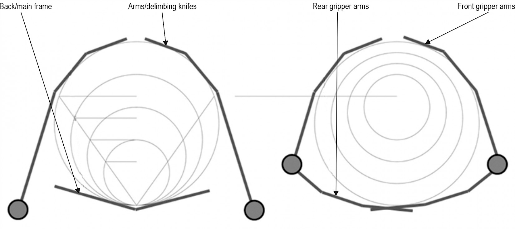
Fig. 4 Comparison of fixation variants of aggregate, left: harvester head and right: felling unit
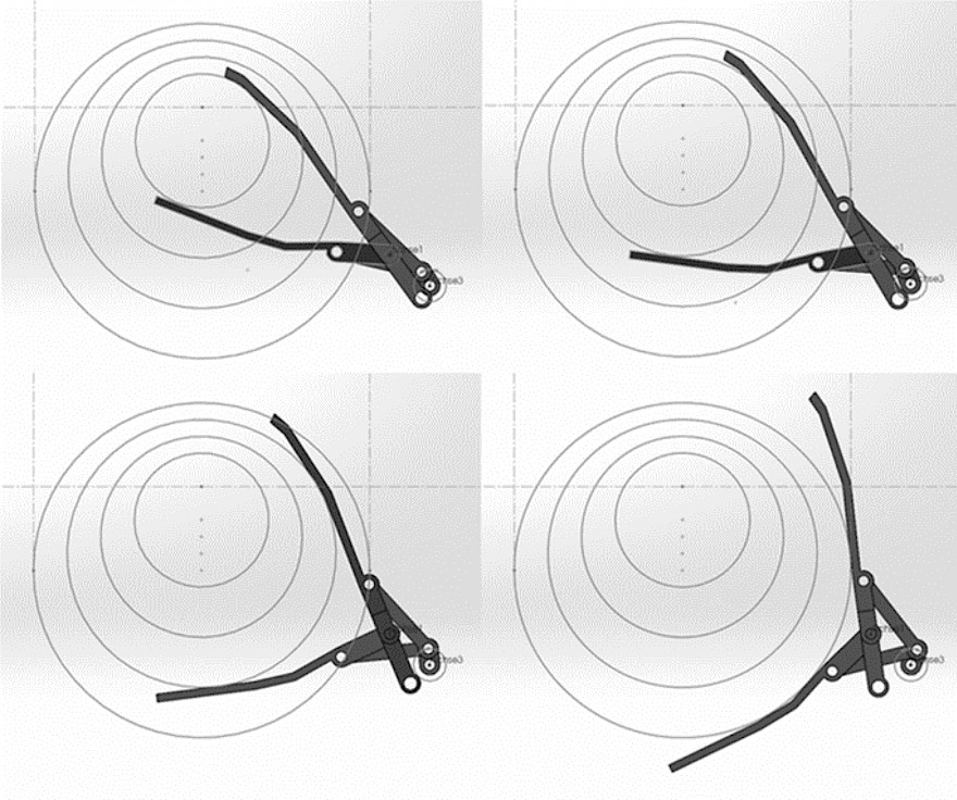
Fig. 5 Head fixation at different tree diameters. In Comparison with Fig. 4 (right), the front gripper arms are shown at the top, the rear gripper arms at the bottom of each image detail
4.2 Creation of Notch
The crawler applies the felling head to the tree on the side opposite to the felling direction. The notch that defines the direction of felling must therefore be sawed on the opposite side of the crawler. This makes it necessary for the saw unit to be located in front of the tree, but to fold away to the side or move away after the felling notch has been cut.
The solution provides that the notching saw can be moved from all required positions by means of two miniature hydraulic cylinders. Sensors detect the position and – later on – help form the notch automatically. In addition, the assemblies for holding the harvester bar, the adjustment of the chain tension, the chain lubrication and the protection against dirt and chain shots were planned and developed.
Normally, the intent was to imitate the process of motor-manual felling. However, here a special feature was introduced that made the notch slightly inclined: Normally the notched roof is sawn at a 45° angle first, while the notch base is then cut horizontally at the level of the cut end of the notch roof. In our felling unit, however, the 45° angle of the felling notch is retained, but it is turned down (around the cutting chord) by –8°. In this way the effect of the notch is fully retained, but the notch slips out by itself. It has been recognized that this is advantageous when felling, as the tree with the stub remaining at an angle receives a counter bearing on which it can support itself; this prevents the tree from sliding backwards. For illustrations of the assembly, see Fig. 6.
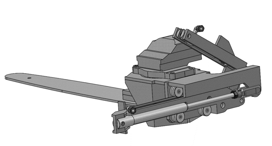
Fig. 6 Notch saw with hydraulic cylinders for adjusting the unit
The entire unit should be repositioned in a rest position, when the machine approaches a tree and places the felling head at the trunk. For this purpose, the notch saw is moved to a rest position in a safe, rearward center via a crooked 3D joint, with the harvester bar moving into a fixed saw box. The joint also offers the option of finely adjusting the end position of the notch saw.
The tests with this notch saw unit were carried out in the factory of Pfanzelt. A special bracket was used to suspend the saw, which ensured that the cuts in the logs were made at the exact angle and depth. The tests have shown that the drive of the saw chain as well as the chain tension and lubrication work technically. Tests with different chain speeds have shown that the best results are achieved at a speed of 30 m/s. The cutting results were very convincing, and the notch fell out on its own in all tests. Fig. 7 shows the test setup and the cutting result.
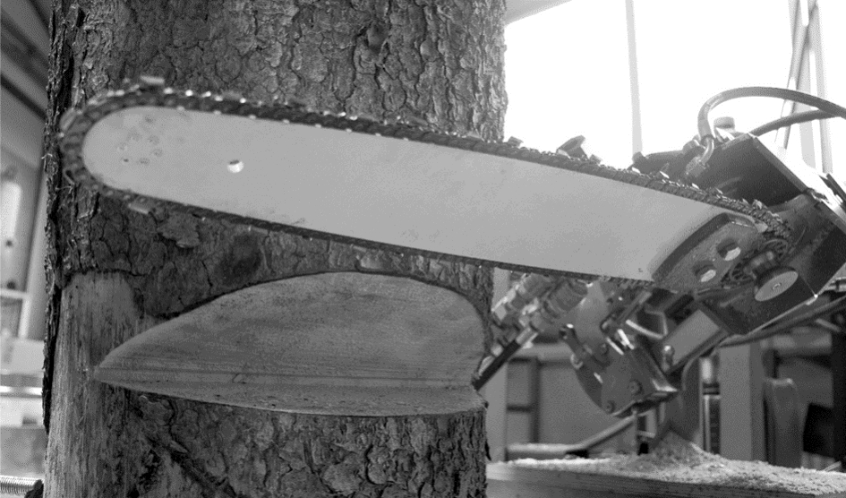
Fig. 7 Cut notch as first test result
4.3 Creation of Felling Cut
The felling cut is carried out by a second, also hydraulically driven, chainsaw with a short harvester bar (Fig. 8, C). With the help of a linear guide, this saw executes a movement parallel to the tangent cutting of the notch saw and leaves a hinge in the required width. The cutting depth of the saw and thus the width of the hinge can be adjusted. The angular position of the saw supports the setting of the wedge and storing the saw. During the cut, the saw moves from one protected saw box to an opposite, also protected, saw box (Fig. 8, A and G). Here, too, the drive is equivalent to the notch saw with a slowly rotating planetary motor and a chain drive. The detailed structure of the chainsaw is similar to that of the notch saw; there is also a high degree of interchangeability and serviceability with the help of standard components. Since a wedge has to be driven into the opening gap during the felling cut, the saw bar is set at a slight angle and position sensors along the linear section ensure that the movements are synchronized (see Fig. 8).
4.4 Tree Wedging
The application of a tilting moment should be done with the help of a drill cone, which is hydraulically driven and acts in the felling cut. This has the advantage that, due to the thread, it turns itself in and cannot slip out, does not need to be readjusted and can be unscrewed again, if needed. It must be set in as soon as the felling saw has completed about half of the felling cut (see Fig. 8, where the felling cut is made from right to left; the grey area of the stem is the already cut felling cut zone). At this point in time, the tree still has enough intact cross-sectional wood area to be stable. Only when the wedge is in place and the saw gap is open, the felling saw can complete the felling cut. Therefore, the drill cone inevitably works closely with the movable felling saw and must sit at the same level.
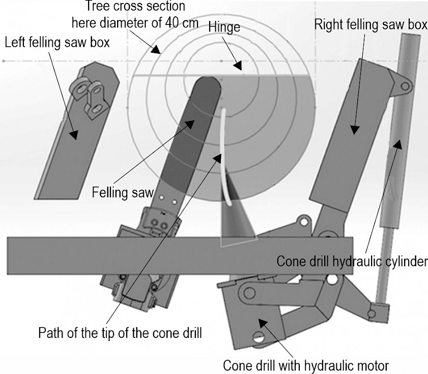
Fig. 8 Interaction of felling saw and drill cone
However, so that the felling saw remains movable from one end position to the other, the drill wedge must be able to be folded away so that it does not protrude far from the unit in the waiting position or even requires a large distance between the unit and the crawler. Since the movement in the felling saw gap has to be linear, a coupling gear was designed. The wedge unit follows a movement that is quasi-linear in the felling cut and turns sharply to the side, outside of the tree.
So far, there has only been one drill cone on the market from the German company Forstreich (Forstreich 2022), which is used to support tree felling. For this reason, cones were also used; they are otherwise used for splitting wood on the so-called cone splitters. Several tests were carried out with cones in three different diameters (50 mm, 70 mm and 80 mm). The absolute torque that must be applied depends on many factors. It has been shown that it is crucial that the resulting hinge between the felling notch cut and the felling cut is not too large. On the basis of the test results, a hydraulic motor with 200 Nm torque was used for the assembly, which offers sufficient reserve for trees that are more difficult to fell. In another paper, our examination to determine the necessary drill cone torque in dependence of the standing moment of the tree and the bending resistance of the hinge was described and the level of friction loss in the cone drill was determined (A scientific article with more detailed information on the dimensioning of the drill cone is currently being submitted).
4.5 Connection of Felling Unit to FR70/75 Forest Crawler
To attach a felling unit with the Moritz FR70/75 forest crawler, a separate manipulation arm had to be developed, which can not only be lifted vertically, but also has a total of five degrees of freedom. Four of them need to be actively controlled, one can be passive. This manipulation arm consists of a flat telescopic crane (telescopic path of 1400 mm and a swivel angle of ±45.5°) as a structure on the forest crawler, which can be rotated and tilted. The felling head at the top of the crane can be rotated through a swivel angle of ±62°; this is necessary so that the felling direction of a tree can also be selected independently of the crawler position. The unit is hanging in the tip of a fork (see Fig. 9).
In interaction with the forest crawler, it can be seen that the felling unit has a small installation space, which is the result of the stringent optimization of the assemblies and their interaction. The functional main parts of the felling unit only weigh around 150 kg. The entire crawler including the felling head weighs around a tenth of a conventional harvester.
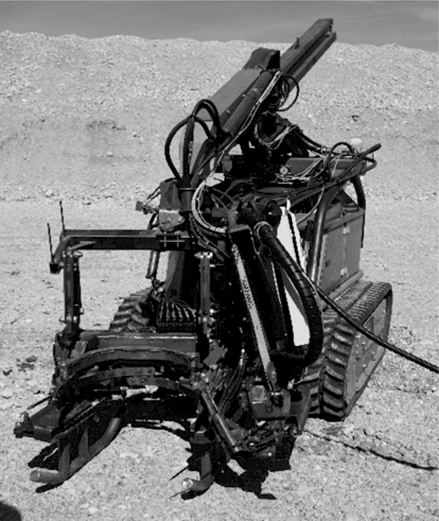
Fig. 9 Ready to use prototype
4.6 Development of Automation Solution
For the process of commissioning and detailed process analysis, the movement sequences, which were partially automated with a PLC (programmable logic controller) control from Siemens, were controlled with the help of a wired operating unit. All parameters and subsystems could be accessed. The felling process takes place fully automatically after the unit has been fixed to the tree, but currently includes two manual confirmations that the forest worker also makes in the same way and are a condition for the controlled tree felling: the confirmation that the felling notch has fallen and that the drill wedge is correctly positioned.
4.7 Field Tests
After completion of the tests in the laboratory, technical reliability was tested under forest conditions. Here, it was possible to analyze in the forest how the machine behaved with the pendulous top load when driving in the terrain (on a slope, across the slope, over knolls, when driving onto the transport trailer, etc.).
First, the felling crawler, operated by a forest contractor, worked in a beetle-damaged coniferous stand that was to be felled in small groups. This was advantageous because there was no danger that the falling tree could be deflected or pushed back by contact with other trees or that it could get caught by another tree (see Fig. 10). Within these tests, more than 100 trees were felled.
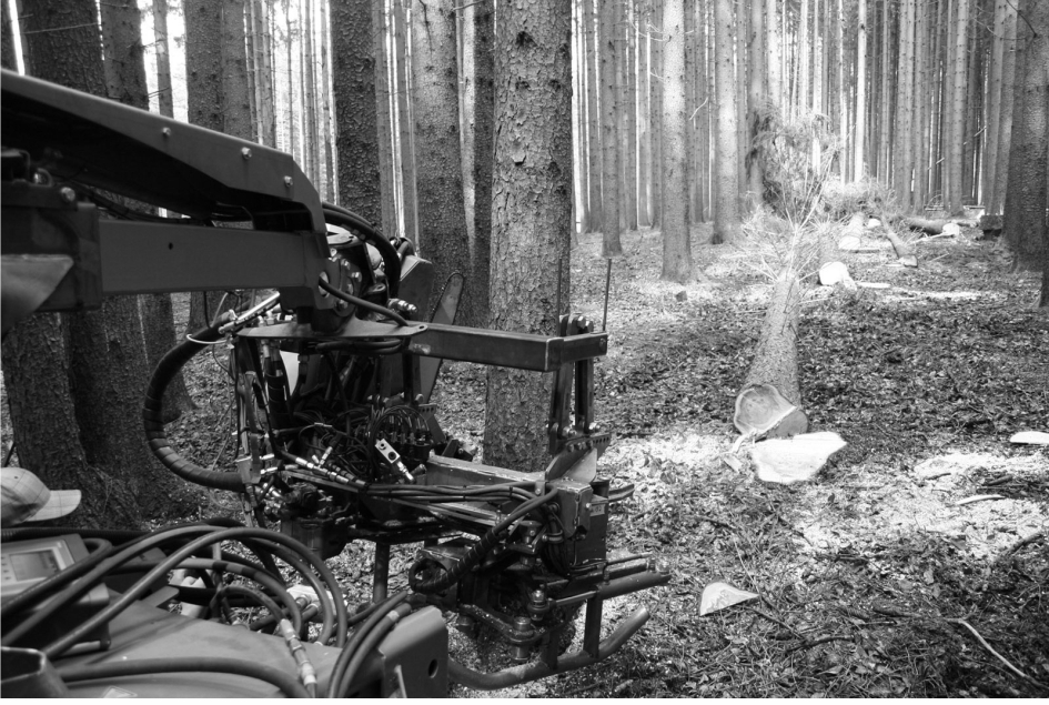
Fig. 10 Field test
In the first test phase, 31 spruce trees (average felling diameter 41 cm) near »Landsberg am Lech« would be felled. It turned out that the modification of the inclination with the fully mechanized installation of the notch (notch base –8°, notch roof +35° to the horizontal) had the advantage that the tree does not slide backwards while falling but retains a sloping support surface and is therefore safely guided for a longer part of the felling operation. The experienced forest contractors were enthusiastic about the accuracy of the felling technique (see Fig. 11). Motor-manual felling operations with too small shaping of the hinge leads to uncontrolled felling movements of the tree. On the other hand, too big hinges may cause exhausting wedge work, combined with the risk of dead branches breaking off the crown space. The Professorship for Forest Technology examined the stock images, the deviations in the felling direction from the target and the cutting geometry. The forest workers praised the speed with which the tree is felled and wedged.
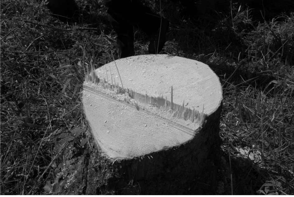
Fig. 11 Stump as a result of field tests with felling head
In a second attempt, 62 additional conifers were felled (average felling diameter: 27.7 cm (Min 19.1, Max 47.5), average distance between trees 4.0 m). In this field test, the focus was less on the functionality of the machine and more on ergonomics, performance and the effects of using the tracks on the forest floor. As part of a bachelor thesis (Bade 2022), the process times of the work were recorded, and the productivity of the felling crawler was determined from this (see Table 1). It turns out that 10 trees can be felled per hour with the existing prototype; it takes about 6 minutes to complete the felling process, including moving from tree to tree and 10% of delay times. It can be estimated that workers familiar with a modified machine can reach up to 14 felling operations per hour. If this productivity is achieved, the costs are comparable with the motor-manual felling; however, the machine felling is much safer. The speed of the crawler with felling head was in the stand 1.2 km/h, on strip roads 3.4 km/h, and on forest roads 5.3 km/h.
Table 1 Average cycle time components of the felling process
|
Cycle time min |
Standard deviation |
|
|
1. Localizing tree |
0.74 |
– |
|
2. Cut free tree/way to tree |
0.82 |
– |
|
3. Driving to the tree |
2.19 |
5.8 |
|
4. Fixation of the unit on the tree |
1.74 |
16.8 |
|
5. Creation of the notch |
0.91 |
6.1 |
|
6. Creation of the felling cut/wedging |
0.60 |
1.3 |
|
7. Time for side jobs |
1.13 |
– |
|
Cycle time (step 3 till step 6 * 1.1) |
5.98 |
– |
At 42% soil moisture (measured at different locations with IMKO EZ-IT and the IMKO Trime Data Pilot), the machine showed a mean contact surface pressure of about 40 kPa and a rutting that did not go beyond the clear height of the chain (about 35 mm, measured with ruler and reference bar). No significant effect on the CO2 volume in the soil compared to the reference measurement could be detected with Vaisala Carbocap GM70, which indicates that the biological soil functions will recover quickly after traffic.
Compliance with the intended direction of fall was achieved with a maximum deviation of ±3°, but in 91% of cases the tree fell exactly in the desired direction (Trees fell in intended direction, but in 9% of cases the trees fell on stumps and jumped sideways). Due to the sloping notch base, the tree was able to »push itself off« from the rootstock, showed no tendency to slide backwards and lied down about a meter in front of the stump. This made it unnecessary for the crawler to reverse in the moment when the tree starts to fall, which was initially envisaged in an automated form. Deviations from the target felling direction and laterally diagonally offset positional deviations of the trunk foot occurred when the tree crown hit on standing trees during the falling process or when the tree hit stumps that were already in place. Since the front shield can be moved independently of the felling head, a subsequent move can be made with the integrated cable winch, if needed.
4.8 Machine specifications
Weight of crawler: 1400 kg
Weight of felling unit: 395 kg
Weight of manipulation arm: 400 kg
Centre of gravity: about 45 cm from the front tip edge.
Maximum felling diameter: 500 mm
5. Discussion
The field tests has shown that it is possible to fell a tree mechanically without the inertia of a huge base machine. With an automated felling process, where a machine mimics the best practice of a lumberjack using a chainsaw, productivity and operator safety can be increased. The first prototype was restricted to a maximum felling diameter of 500 mm. In a next step, the felling diameter will raise up to 800 mm (without huge impact to the deadweight of the felling head itself), where the effects of a better productivity and security will be significantly improved.
The necessary torque of the cone drill drive was controlled, but because of the comparative small trees of the field tests, it is not yet possible to make a statement about the torque peaks that are then expected. The forceful insertion of the drill cone was usually enough to cause the tree to fall after the felling cut had been completed.
In order to implement the mechanical imitation of the motor-manual tree harvest, it is necessary to introduce a cutting geometry dependent on the tree diameter. If this geometry is to be created with a hydraulic chain saw, the tree to be felled could be fixed relative to the unit – as is known with harvester units. Depending on the diameter of the tree, the saw would then have to be adjustable several times and regulated by a complex control system.
The concept implemented in the felling head presented provides that all tools for notching and felling cuts are aligned purely mechanically and automatically to the tree axis and are fixed to the main frame. Also, the chainsaw cuts with the incoming chain instead of the tip. A patent has been registered for this solution.
The field tests showed in detail the need for some technical and control improvements. It was planned to use the prototype in hardwood also, but in the test phase, it was not possible to realize this plan because of the wood price situation specified by local regulations.
6. Outlook
The main use of the felling crawler is to substitute the forest worker at the felling job of huge hardwood trees with unstable crown at comparable hourly costs.
Furthermore, the use of the felling crawler can be seen in three additional forest harvesting options (calculations based on our test results).
The first option (see Fig. 12) is a fully mechanized cut to length method with 40 m to 60 m spacing between the strip roads. Here, a harvester fells and processes the trees to be removed on both sides along the strip road in the crane zone. Then the felling crawler cuts the trees in the intermediate zone towards the direction of the strip roads. In a third run, the harvester drives again on the strip roads and processes the trees, which are felled by the felling crawler. All trunk segments lying at the strip road are then moved by a forwarder to the forest road.
The costs of the total procedure are estimated to 20.84 EUR/m3, of which the felling with the crawler costs 3.29 EUR/m3. Costs of motor-manual felling operations are roughly the same.
From an ecological point of view, the process is suitable for dry to wet soils. While the crawler drives on the soil outside the strip roads, the low ground pressure of the caterpillars allows the driving on the soil without limitation, as long as it leaves out areas with natural regeneration. With this option, large areas remain undivided by strip roads, which has positive effects on the silvicultural freedom of the forester. Since the option cuts the logs to length and uses forwarders for transport purposes, the well-known positive aspects of ctl-methods can be assumed, too.
From a social point of view, the fully mechanized process shows a high level of working safety. The crawler operator can stay outside the danger area with his radio remote control. The mental stress can be considered at low level.
As an option, the felling crawler can be used with its integrated winch to pre-skid to the strip road the trunks that do not protrude into the crane zone of the harvester. By this, the option shows a wide flexibility.
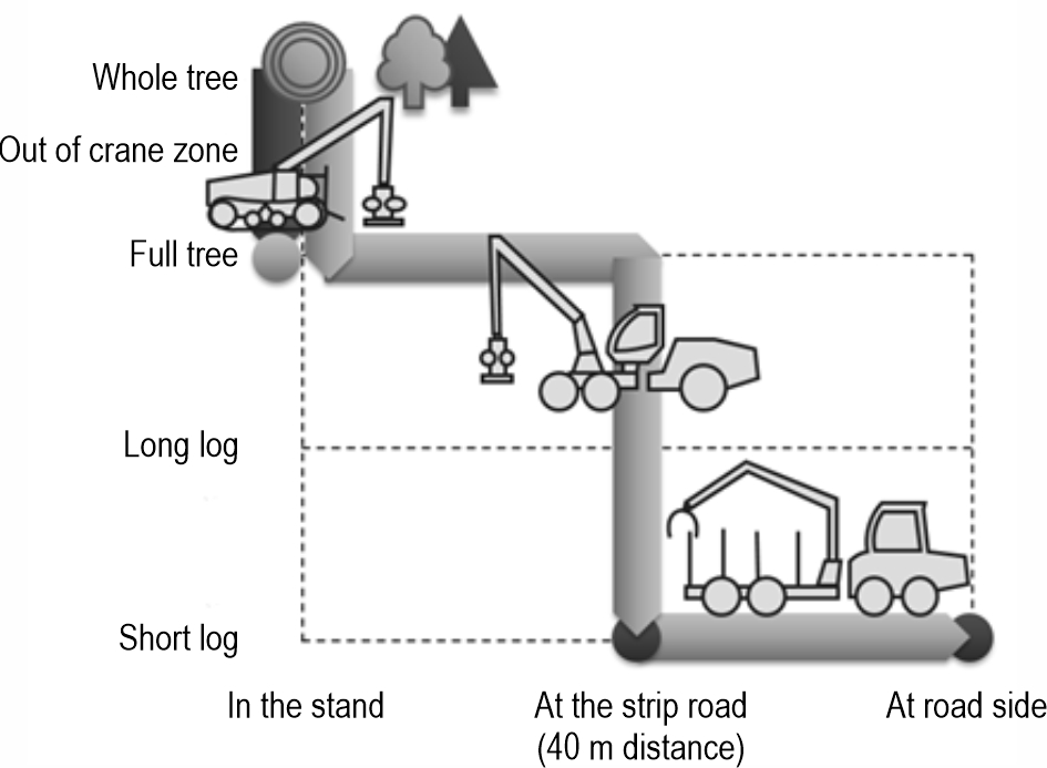
Fig. 12 Process option I. Fully mechanized cut to length method
The second option (see Fig. 13) is a fully mechanized full tree method with a cable yarder. It can be used in situations where the area is generally accessible, but where large forest machines are not allowed to or cannot drive on the soil so that consequently the wood extraction has to be done by cable yarders.
With this method, the cable line can be opened up by the felling crawler, and the trees to be removed near to the line are felled by the crawler. On the way back, while the cable line is built up, the felling crawler cuts the trees in the area outside of cable corridor. If needed, the operator of the crawler can delimb the felled trees with a cordless electric saw, which can be recharged on the crawler. In addition, the felling crawler can be used for pre-skidding of the trees that are too far away from the cable line to improve the productivity of the much more expensive cable yarder. Later on, when the full trees (and partly delimbed trees) arrive at the forest road, a processor takes over the processing and a forwarder transports the short logs to the loading site and stores them on piles.
For this procedure, costs of 41.09 EUR/m3 are estimated, which is mainly depending on the tree dimensions. The costs of the crawler in this method are about 6.67 EUR/m3.
From the ecological point of view, the entire area has no contact with large and heavy forest machines, with only the crawler driving there. It should save areas where the regeneration takes place; normally, the skidding of long logs makes some damage to the stands, but this is mostly limited on the area around the cable line.
The social analysis of the fully mechanized process shows a high level of work safety, as the crawler operator can stay outside the danger area with his radio remote control; therefore, it is not absolutely necessary to work in a group.
Individual steps of the work with the cable yarder are considered heavy work, and the mental strain on the machine operator of the crawler is also rated as high.
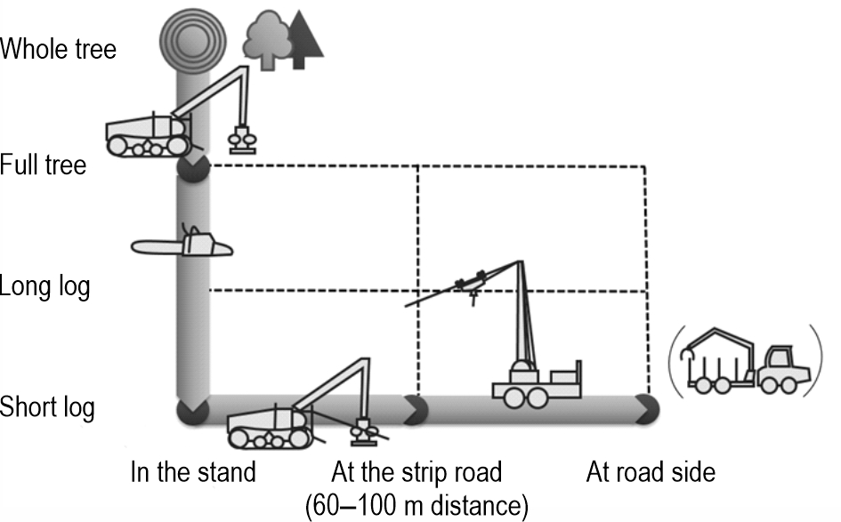
Fig. 13 Process option II. Semi-mechanized cut to length method
The third process (see Fig. 14), in which the forest crawler with felling unit can be depicted, is a semi-mechanized cut to length method with machine felling. While process option I can be used more for softwood due to the use of a harvester, process option III is also interesting for hardwood harvesting.
The felling crawler fells all trees between the strip roads, namely the trees standing near the strip road towards that lane, but trees far away from the skidding lane in the opposite direction. The crawler has to proceed on the entire width between two strip roads, as the trunks and crowns clog the area and prevent a return journey. Near to the crawler, two additional forest workers delimb, top and if needed crosscut the trees motor-manually. The crawler afterwards skids the tree lengths or short logs to the crane zone of the forwarder that transports them to the storage location.
The resulting costs amount to 37.76 EUR/m3, with the felling of the crawler of 6.16 EUR/m3 as well as pre-skidding with the crawler of 20.00 EUR/m3.
The method can be limited by natural regeneration, which must be saved.
A socially positive assessment of this process is that the accident-prone felling of the trees is fully mechanized, and the operator is outside the danger zone. However, this method requires a motor-manual processing of the felled trees near to the felling operations, which can be dangerous.
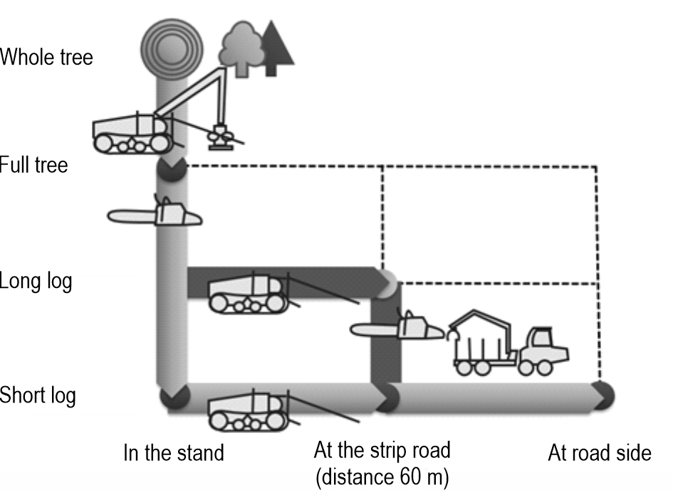
Fig. 14 Process option III. Semi-mechanized cut to length method
7. Patents
A patent application has been filed for the functional principle. The patent draft is currently being examined.
Acknowledgments
This project was funded by ZIM (central innovation program for medium-sized companies). The Projectnumber is: 16KN079421.
Appendix A
The parameters below, such as machine costs and performance data, refer to the values given in KWF, 2022.
Table A1 Process calculation process option I
|
Stage 1: Fully mechanized felling and processing with harvester |
||
|
Performance |
16 |
Cubic meter of timber harvested with bark (chb) per hour |
|
Machine costs per hour |
188 |
EUR/h |
|
Total time per hectar |
2.47 |
h |
|
Costs per chb |
11.75 |
EUR/chb (on every second strip road) |
|
Stage 2.1: Felling with crawler |
||
|
Average distance tree-tree |
16 |
meter |
|
Positioning/felling time per tree |
195 |
seconds per tree |
|
Trees per hour |
14.20 |
trees/h |
|
Performance |
30.39 |
chb/h (2.14 chb per tree, spruce) |
|
Costs per chb |
3.29 |
EUR/chb (on every second strip road) |
|
Stage 2.2: Processing with harvester |
||
|
Performance of processing |
16 |
chb/h |
|
Machine costs per hour |
188 |
EUR/h |
|
Total time per hectar |
2.47 |
h |
|
Costs per chb |
11.75 |
EUR/chb (on every second strip road) |
|
Stage 3: Extraction with forwarder |
||
|
Performance of extraction |
16 |
chb/h |
|
Machine costs per hour |
119 |
EUR/h |
|
Total time per hectar |
4.95 |
h |
|
Costs per chb |
7.45 |
EUR/chb |
|
Total costs per chb |
20.84 |
EUR/chb |
Table A2 Process calculation process option II (200 chb of beech)
|
Stage 1: Felling of cable line with crawler (4 m wide) |
||
|
Average distance tree-tree |
5 |
meter |
|
Positioning/felling time per tree |
195 |
seconds per tree |
|
Performance |
14.77 |
chb/h (1 chb per tree, beech) |
|
Costs per chb |
6.77 |
EUR/chb |
|
Stage 2: Set up of cable yarder |
||
|
Per set up |
1000 |
EUR |
|
Costs |
5 |
EUR/chb |
|
Stage 3.1: Felling with crawler |
||
|
Average distance tree-tree |
12 |
meter |
|
Positioning/felling time per tree |
195 |
seconds per tree |
|
Performance |
14.77 |
chb/h |
|
Costs per chb |
6.77 |
EUR/chb |
|
Stage 3.2: Extraction with crawler |
||
|
Performance |
8 |
chb/h |
|
Costs per chb |
13 |
EUR/h |
|
Stage 4: Extraction with cable yarder |
||
|
Machine costs per hour |
156 |
EUR/chhb |
|
Performance |
12 |
chb/h |
|
Costs per chb |
13 |
EUR/chhb |
|
Stage 5: Extraction with forwarder (is needed half a day) |
||
|
Machine costs per hour |
60 |
EUR/chhb |
|
Performance |
12 |
chb/h |
|
Costs per chb |
5 |
EUR/chhb |
|
Total costs per chb |
41.09 |
EUR/chb |
Table A3 Process calculation process option III (beech)
|
Stage 1: Felling with crawler |
||
|
Positioning/felling time per tree |
195 |
seconds per tree |
|
Performance |
16.25 |
chb/h (1.1 chb per tree, beech) |
|
Costs per chb |
6.16 |
EUR/chb |
|
Stage 2: Motor-manual delimbing (38.00 EUR/h) |
||
|
Performance per forest worker |
5 |
chb/h |
|
Number of forest worker |
2 |
– |
|
Total performance per hour |
10 |
chb/h |
|
Costs per chb |
7.6 |
EUR/chb |
|
Stage 3: Preskidding with crawler (average skidding distance: 20 m) |
||
|
Machine costs per hour |
88 |
EUR/chb |
|
Performance |
5 |
chb/h |
|
Percentage of skidded wood |
66 |
% |
|
Costs per chb |
20 |
EUR/chb |
|
Stage 4: Extraction with forwarder (is needed half a day) |
||
|
Machine costs per hour |
119 |
EUR/chhb |
|
Performance |
10 |
chb/h |
|
Costs per chb |
12 |
EUR/chhb |
|
Total costs per chb |
37.76 |
EUR/chb |
6. References
Bade, C., 2022: Produktivitätsstudie eines neuartigen Fällaggregates an einer Forstraupe (Productivity study of a new type of felling head on a forest crawler), 2022. Bachelor-thesis. Technische Universität Dresden, Tharandt.
Badgujar, C., Flippo, D., Badua, S., Baldwin, C., 2023: Development and Evaluation of Pasture Tree Cutting Robot: Proof-of-Concept Study. Croatian journal of forest engineering 44(1): 1–11. https://doi.org/10.5552/crojfe.2023.1731
Berendt, F., Fortin, M., Suchomel, C., Schweier, J., 2018: Productivity, costs, and selected environmental impacts of remote-controlled mini forestry crawlers. Forests 9(10): 591. https://doi.org/10.3390/f9100591
Bomford Turner Ltd. 2019: Accessories for Flailbot. Front-End Loader. Available online: https://www.bomford-turner.com/product/front-end-loader/ (accessed 18 Jan 2022).
Forstreich, 2022: Drillkegel (Cone Drill) Forstreich GmbH. Available online: https://www.forstreich.de/produkt/forstreich-drillkegel/ (accessed 18 Jan 2022).
Friedrich, A., 2019: Mulcherpflege (mulchercare). Forst&Technik (5/2019): p. 35f.
FSC (Forest Stewardship Council), 2018: German FSC Standard. FSC Germany (Producer). Available online: https://www.fsc-deutschland.de/de-de/wald/waldstandards (accessed 18 Jan 2022).
German Federal Ministry of Food, Agriculture and Consumer Protection, 2011: Forest Strategy 2020. Sustainable Forest Management – An Opportunity and a Challenge for Society. Available online: https://www.bmel.de/SharedDocs/Downloads/EN/Publications/ForestStrategy2020.pdf (accessed 18 Jan 2022).
KWF (Board of trustees for forest work and forest technology), 2020: Final report of the project »Best harvest«. Available online: https://kwf2020.kwf-online.de/wp-content/uploads/2022/04/Abschlussbericht-BestHarvest-2022-02-28.pdf (accessed 10 Feb 2023).
Labelle, E.R., Breinig, L., Sycheva, E., 2018: Exploring the use of harvesters in large-diameter hardwood-dominated stands. Forests 9(7): 424. https://doi.org/10.3390/f9070424
Mederski, P.S., Schweier, J., Đuka, A., Tsioras, P., Bont, L.G., Bembenek, M., 2022: Mechanised Harvesting of Broadleaved Tree Species in Europe. Current Forestry Reports 8(1): 1–19. https://doi.org/10.1007/s40725-021-00154-7
Michels, L., 2017: Die Ermittlung von Unfallschwerpunkten in der Forstwirtschaft (The determination of accident black spots in forestry). PHD Thesis, Technische Universität Dresden, Tharandt. Available online: https://tud.qucosa.de/api/qucosa%3A30337/attachment/ATT-0/ (accessed 18 Jan 2022).
Pfanzelt, 2022: Moritz Fr70/75 PM Pfanzelt Maschinenbau GmbH. Available online: https://www.pfanzelt.com/de/faellraupe/forstraupe-moritz-fr70-75 (accessed 18 Jan 2022).
Pfenninger, M., Reuss, F., Kiebler, A., Schönnenbeck, P., Caliendo, C., Gerber, S., Cocchiararo, B., Reuter, S., Blüthgen, N., Mody, K., Mishra, B., Bálint, Thines, M., Feldmeyer, B., 2021: Genomic basis for drought resistance in European beech forests threatened by climate change. Elife 10: e65532. https://doi.org/10.7554/eLife.65532
Sanktjohannser, D., 2019: Harvesterköpfe zur Bearbeitung von Laubholz – Aktuelle Literaturübersicht (harvesterheads for hardwood – current overview). Bachelor thesis, Technische Universität Dresden, Tharandt.
Scott, D.A., 2014: Tree Felling Attachment. Patent number: NZ717787. A01G23/091; A01G23/08; A01G23/009.
© 2023 by the authors. Submitted for possible open access publication under the
terms and conditions of the Creative Commons Attribution (CC BY) license (http://creativecommons.org/licenses/by/4.0/).
Authors' addresses:
Christian Knobloch, PhD *
e-mail: christian.knobloch@tu-dresden.de
Prof. Jörn Erler, PhD
e-mail: joern.erler1@tu-dresden.de
Lars Richter, MSc
e-mail: lars.richter.forst@gmail.com
Technische Universität Dresden
Faculty of Environmental Sciences
Department of Forest Sciences
Professorship for Forest Technology
Dresdner Straße 37
01737 Tharandt
GERMANY
Paul Pfanzelt
e-mail: info@pfanzelt.com
PM Pfanzelt Maschinenbau GmbH
Frankau 37
87675 Rettenbach am Auerberg
GERMANY
* Corresponding author
Received: March 8, 2022
Accepted: March 3, 2023
Original scientific paper