Using Cyclic CBR Method to Determine Resilient Modulus of Hydraulic Binder Stabilised Road Pavement Base Layers
doi: 10.5552/crojfe.2024.2214
volume: 45, issue:
pp: 13
- Author(s):
-
- Primusz Péter
- Kisfaludi Balázs
- Péterfalvi József
- Article category:
- Original scientific paper
- Keywords:
- cyclic CBR, resilient modulus, load bearing capacity, mechanistic-empirical design, soil stabilisation, FWD
Abstract
HTML
The mechanistic-empirical (E-M) design of pavement structures requires knowledge of the elastic modulus of the layers comprising the structure. The necessary cyclic (dynamic) triaxial testing is expensive and cumbersome for low-volume forest and agricultural roads. Opiyo (1995) developed a method called cyclic CBR (cCBR) to determine the resilient modulus (Mr) of granular road construction materials using CBR testing equipment. The present study tested the cCBR method on silty, fine sand stabilised with lime and a lime-cement mixture. For the test, 24 test specimens were prepared by adding 3, 5 and 7% pure lime and a 70–30 lime-cement mixture at the targeted 8–23% water content. Three metrics were used to express the bearing capacity of the specimens: (1) the commonly used CBR% value, (2) the Mr value calculated as a function of load force and elastic deformation determined as a result of the cCBR test, and (3) the resilient modulus calculated from the CBR value. The experimental results showed that the initial water content had a greater effect on the bearing capacity than the binder dosage. The present study found the cCBR procedure to be feasible. The test results were converted to a resilient modulus value using the formula developed by Opiyo and Molenaar, respectively. The calculated resilient modulus values from the CBR value exhibited a wide variation. Uzan’s formula provided similar results to those calculated by Molenaar’s formula. A 250 m long experimental road section was also constructed to verify the laboratory data. Based on the laboratory tests, five different 50 m long stabilisation layers were built. The bearing capacity data measured with the handheld BC-1 LFWD and KUAB-FWD equipment verified Molenaar’s formula.
Using Cyclic CBR Method to Determine Resilient Modulus of Hydraulic Binder Stabilised Road Pavement Base Layers
Péter Primusz, Balázs Kisfaludi, József Péterfalvi
Abstract
The mechanistic-empirical (E-M) design of pavement structures requires knowledge of the elastic modulus of the layers comprising the structure. The necessary cyclic (dynamic) triaxial testing is expensive and cumbersome for low-volume forest and agricultural roads. Opiyo (1995) developed a method called cyclic CBR (cCBR) to determine the resilient modulus (Mr) of granular road construction materials using CBR testing equipment. The present study tested the cCBR method on silty, fine sand stabilised with lime and a lime-cement mixture. For the test, 24 test specimens were prepared by adding 3, 5 and 7% pure lime and a 70–30 lime-cement mixture at the targeted 8–23% water content. Three metrics were used to express the bearing capacity of the specimens: (1) the commonly used CBR% value, (2) the Mr value calculated as a function of load force and elastic deformation determined as a result of the cCBR test, and (3) the resilient modulus calculated from the CBR value. The experimental results showed that the initial water content had a greater effect on the bearing capacity than the binder dosage. The present study found the cCBR procedure to be feasible. The test results were converted to a resilient modulus value using the formula developed by Opiyo and Molenaar, respectively. The calculated resilient modulus values from the CBR value exhibited a wide variation. Uzan's formula provided similar results to those calculated by Molenaar's formula. A 250 m long experimental road section was also constructed to verify the laboratory data. Based on the laboratory tests, five different 50 m long stabilisation layers were built. The bearing capacity data measured with the handheld BC-1 LFWD and KUAB-FWD equipment verified Molenaar's formula.
Keywords: cyclic CBR, resilient modulus, load bearing capacity, mechanistic-empirical design, soil stabilisation, FWD
1. Introduction
Forest areas opened by low volume, unpaved roads pose a major challenge for foresters as weather heavily influences the ability to transport timber on these roads. This is particularly true in Hungary in the light of climate change where the decreasing number of frosty days renders roads largely unfit for transport during the logging season. Paving – macadam or asphalt – a conventional dirt road requires a significant financial investment, which is not always available. Therefore, foresters continuously search for cost-efficient road structure solutions that significantly extend the trafficable period.
Using local materials can significantly reduce the construction costs of pavement structures. Adding a binder with the correct physical properties can make local soils workable and load bearing. When soils are stabilised, the water absorption of the cohesive layer mixed with the binder is reduced, making the stabilised soil less susceptible to water. This means that a stabilised layer with a higher bearing capacity can durably support the pavement layers, regardless of weather conditions. Different soil types require different binders to achieve technically appropriate and optimally producible soil stabilisation. Quicklime binders are the most favourable for cohesive soils such as clays and silts, while cement is optimal for sandy soils. The choice of binders must consider technical, economic, and environmental aspects (Åhnberg et al. 2003). However, the cost of the binder is one of the main deciding factors for low-volume roads. Therefore, several types of binders should be tested, especially for intermediate soils. The literature recommends hydraulic road binders produced from a cement and quicklime mixture for the so-called intermediate soils between granular and cohesive soils (Solanki et al. 2010, Szendefy 2017). Sirivitmaitrie et al. (2011) investigated the resilient modulus of lime and lime-cement stabilised expansive soils at three test sites. The resilient modulus test results show that combined lime-cement treated soils have yielded the highest Mr enhancements when compared with lime-treated and control soils. In several cases, soils treated with lime alone did not fall far below the lime-cement mixture. The reason for this is that we cannot be sure that cement, or rather lime, will work better as a binder in intermediate soils (Åhnberg et al. 2003).
The load-bearing capacity of stabilised local soil is not considered in conventional public road construction, but in forest road construction it is frequently considered as the load-bearing part of the road structure. Therefore, particular attention should be paid to the design and construction of economical, low-cost road structures. The low construction costs of forest roads compared to public roads are generally insufficient to cover the high design costs. In his review article, Heinimann (2021) summarised the development and main challenges of pavement design systems for forest roads. With the development of computer technology and the increasing knowledge of materials, designers can now employ the novel mechanical-based pavement design method using precise material parameters instead of the empirical CBR (California Bearing Ratio) methods. This rational design method models the pavement structure with a system of superimposed elastic plates (or layers). The response of the plate system to a load can be calculated as a function of the material parameters describing the elasticity of the plates and the relationship between the plates (Ioannides and Khazanovich 1998). A key point of rational pavement design is to determine the bearing capacity of the subgrade with sufficient accuracy. Therefore, Heinimann (2021) highlights the need to improve the conversion of simple soil bearing capacity, such as CBR, to the elastic modulus.
Cyclic (dynamic) triaxial testing can directly determine the material parameters required for mechanically based pavement design, but the test is complex and requires expensive equipment (Araya et al. 2010). Several authors have attempted to recalculate the results of simpler tests (CBR, unidirectional compression testing), but the recalculated results revealed significant differences. Opiyo (1995) advanced this field by developing the cyclic CBR procedure, which allowed CBR equipment to determine the elastic (resilient) behaviour of soil samples. The method can greatly contribute to the cost-effective mechanical-based design of stabilisation pavement structures for low-volume roads (Ševelová et al. 2021). Therefore, this study compares the strength parameters of a soil stabilisation base course ascertained in the laboratory by cyclic CBR with the field results of a real experimental road section.
2. Materials and Methods
2.1 Theoretical Background
In Hungary, the pavement design method is based on a catalogue system of pavement structures. The original AASHO (American Association of State Highway Officials) method implemented in 1961 has been adopted in forest road design where the bearing capacity of the soil is considered via the CBR value. This value is a ratio that shows the bearing capacity of the material being tested compared to the bearing capacity of a standard crushed stone roadbed. The bearing capacity is defined as the force required to press a 50 mm diameter metal cylinder in 2.5 mm depth at a speed of 1.27 mm/sec into the soil sample prepared to the standards. From the measured force, the CBR can be calculated using Eq. (1).
 (1)
(1)
Where:
F2.5 force required for 2.5 mm penetration, kN
F5.0 force required for 5.0 mm penetration, KN.
The higher of the two CBR values is used according to the standard. Performing the test requires a load frame and a force and displacement gauge. These tools are available in most soil and road laboratories and are used routinely.
An alternative pavement design method that allows for a mechanics-based design was developed in Hungary in 2018 (Tóth and Primusz 2020). The elastic modulus of the pavement layer material is required as an input parameter. For soils, the elastic modulus E, which can be considered under dynamic loading, is well estimated by the Mr resilient modulus. The resilient modulus can be described as the ratio of the deviator stress to the elastic deformation, the magnitude of which depends on the lateral pressure. In addition to the stress state, the value of the resilient modulus is also significantly influenced by the water content and temperature distribution of the subgrade, for which several methods have been developed (Zapata et al. 2007).
The resilient modulus is determined directly by using cyclic (dynamic) triaxial testing equipment. During the test, the specimen is subjected to a rapid (0.1 s) cyclic axial load with constant cell pressure. This allows for the realistic loading modelling of the pavement structure where fast-moving vehicles load a point on the structure for a similarly short period. The equipment used for this test is expensive and more complex to use than CBR equipment and is, therefore, less widely applied. To determine the resilient modulus for mechanics-based design, it seemed straightforward to look for a correlation between the easily determined CBR% and the value of the Mr resilient modulus. Researchers have developed several models to convert the CBR value into a resilient modulus value. Three types of models have been applied:
linear
exponential
polynomial.
Table 1 presents the conversion formulae. It is important to note that the application of the formulae is proposed for specific soil types and CBR ranges; thus, the resilient modulus values calculated by the models sometimes show a large variance.
In the classical CBR test, the test specimen undergoes both plastic and elastic deformation under one load. Therefore, Opiyo (1995) assumed that elastic properties cannot be purely inferred from this one value, i.e., the CBR value cannot be reliably converted into elastic modulus. In 1995, Opiyo developed the cyclic CBR test method to determine the elastic modulus of soils and granular road construction materials using simple existing tools. Other researchers have successfully applied the test to cohesive and stabilised soils (Sas et al. 2012, Sas and Głuchowski 2013).
Table 1 Various conversion formulae from CBR to resilient modulus
|
Type |
Developer of the model |
Conversion formula |
Range |
|
Linear |
Heukelom and Klomp (1962) |
Mr=10.340∙CBR |
10–20 CBR% |
|
Ohio DOT (2008) |
Mr=8.274∙CBR |
||
|
Exponential |
Green and Hall (1975) |
Mr=37.268∙CBR0.711 |
2–200 CBR% |
|
Paterson and Maree (1978) |
Mr=20.670∙CBR0.650 |
||
|
Powell et al. (1984) |
Mr=17.616∙CBR0.640 |
2–12 CBR% |
|
|
Uzan (1985) |
Mr=91.226+0.017∙CBR2 |
||
|
Webb and Campbell (1986) |
Mr=21.470∙CBR0.478 |
||
|
Hopkins (1994) |
Mr=17.914∙CBR0.874 |
||
|
Polynomial |
Kenya Road Design Manual (1987) |
Mr=0.0162∙CBR3-0.5454∙CBR2+10.062∙CBR |
|
|
Mukabi (2016) |
Mr=0.0022∙CBR3-0.1273∙CBR2+6.4261∙CBR |
<170 CBR% |
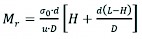
Additional load repetitions are recommended after the first step of the CBR test (2.5 mm penetration at a speed of 1.25 mm/min) (Fig. 1). Repetitions should be performed at the maximum load achieved in the first step (Sparsha et al. 2016). With repeated loads, the material undergoes progressively lesser permanent deformation. The load repetition cycles should theoretically be continued until the specimen shows only elastic deformation. In practice, it is appropriate if the combined permanent deflection of the last five cycles is less than 2% of the total permanent deflection. This condition is typically reached after 50–100 load cycles (Araya 2011, Molenaar 2011, Hao and Pabst 2020), though in other studies 10 cycles were enough (Sparsha et al. 2016). Elastic deformation is well-characterised by the deformation measured in the last load cycle and the force that induces it. Researchers have developed several equations to determine the resilient modulus using these two variables and some auxiliary parameters. Eq. (2) presents the original relationship of Opiyo (1995).
 (2)
(2)
Where:
Mr resilient modulus, MPa
σ0 average compressive stress, MPa
d diameter of load bearing surface, mm
u elastic deformation, mm
L height of sample, mm
H height of cone, mm
D sample diameter, mm.
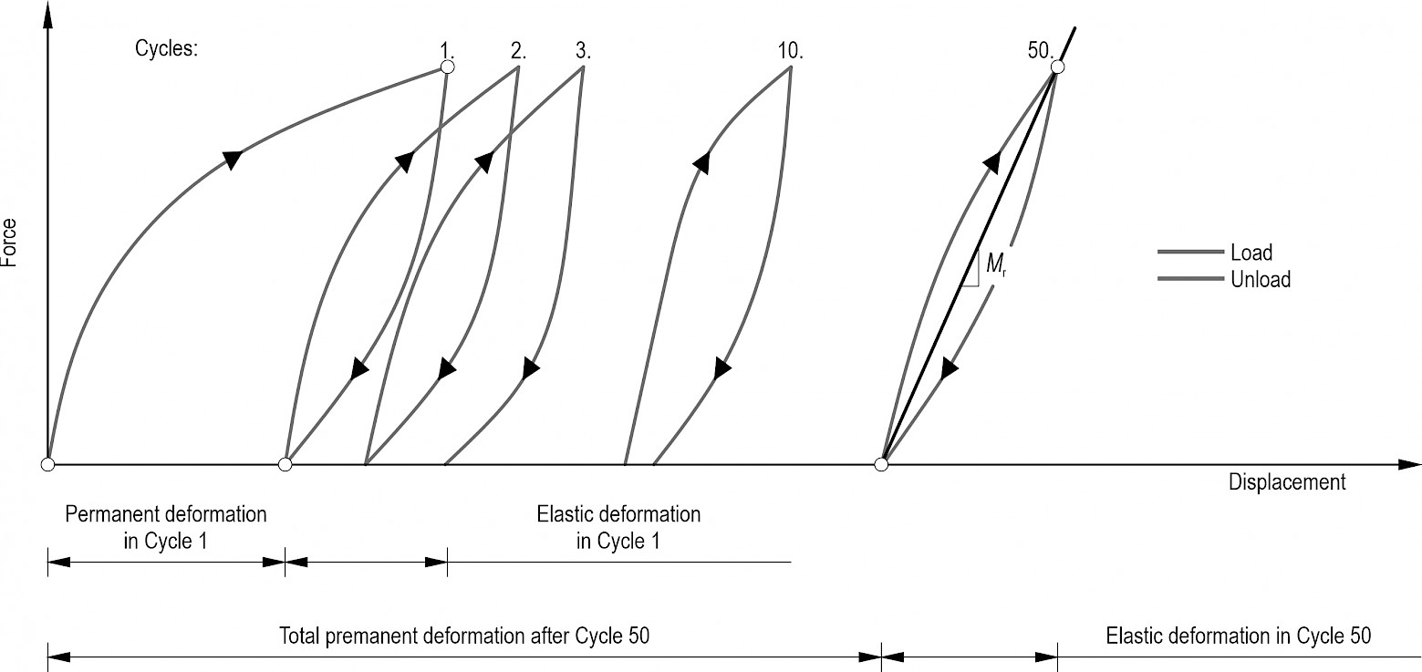
Fig. 1 Schematic force-displacement chart of cyclic CBR test
When the angle of load propagation is assumed to be α=45°, the value of H will be equal to 0.5 (D–d)=50 mm. Molenaar (2011) developed an improved version of Opiyo's (1995) Eq. (3) by considering the friction between the soil and the mould.
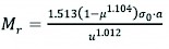 (3)
(3)
Where:
Mr resilient modulus, MPa
µ Poisson's ratio, -
σ0 average compressive stress, MPa
υ elastic deformation, mm
a radius of load surface, mm.
For a precise interpretation of the variables used in this context, see Fig. 2.
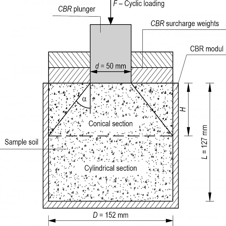
Fig. 2 Interpretation of dimensions used in processing cyclic CBR test (Opiyo 1995)
2.2 Sample Area
The soil stabilisation studies were conducted in the framework of a comprehensive study for which the Egererdő Forestry cPlc. provided the site. Cohesive soils, which are unfavourable for road construction, characterise the company's forestry in Parádfürdő. For the laboratory tests, 300 kg of soil sample were taken from a problematic road section of the »Glóbuszi« forestry road. Fig. 3 depicts the exact location of the sampling.
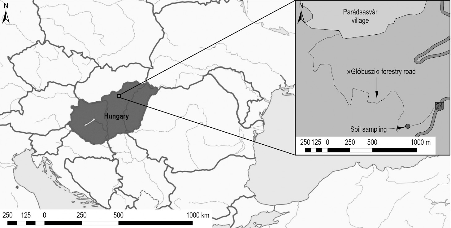
Fig. 3 Soil sampling and location of experimental test sections
2.3 Laboratory Tests
2.3.1 The Soil Tested
The soil was subjected to the soil mechanics tests needed for soil identification. The soil liquid limit (WL) was 40.71%, the plastic limit was (WP) 22.85%, and the plasticity index (IP) was 17.86%. Fig. 4 shows the grain-size distribution curve of the soil. The plasticity index identified the tested soil as lean clay, while the grain-size distribution curve identified it as silty, fine sand. The soil is most compactable at a water content of 15.8%, with a maximum bulk density of 1.81 g/cm3. Based on literature data, the expected resilient modulus of the soil is in the range of 60–100 MPa (Drumm et al. 1990, Bandara and Rowe 2003).
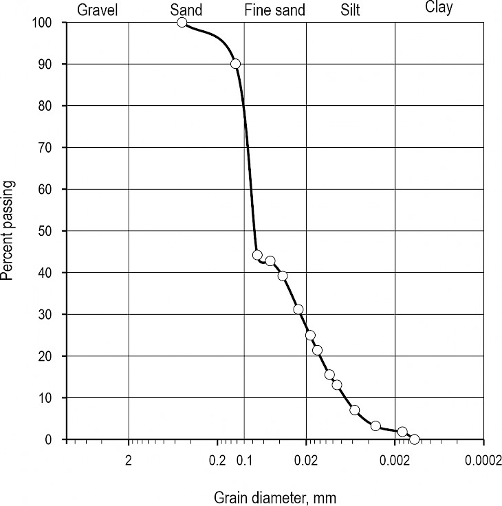
Fig. 4 Grain-size distribution curve of tested soil
2.3.2 Preparation of Test Specimens
The soil sample was air-dried and ground for laboratory testing. Twenty-four mixtures were produced from the prepared soil by adding binder and water according to Table 2. Based on the particle composition and the plasticity index of the soil, both lime and lime-cement mixtures were considered binders. The preliminary experiments were conducted after three days of resting, and the soil showed that the lime-cement mixture resulted in 15–20% higher bearing capacity; therefore, more specimens of this type of binder were tested. The soil mixtures were prepared in CBR moulds (diameter=152 mm, height=127 mm). The mixtures were compacted in five layers in a Proctor compactor with 25 strokes per layer. Finally, the samples were left to stand in a vapour barrier for 28 days.
2.3.3 Cyclical CBR Testing
After resting, the upper plane of the CBR specimens was loaded with a 50 mm diameter steel cylinder moving at a speed of 1.25 mm/min with the Multiensayo universal loading device until a penetration depth of 2.50 mm was reached (Fig. 5a). After unloading, 50 load cycles were applied with the maximum force required for penetration. During the test, the displacement of the load head was recorded as well as the force required to displace it. The maximum force F measured in the first cycle was used to calculate the CBR% of the samples using Eq. (1). Depending on the u elastic deformation measured in the last cycle and the loading force, Opiyo's resilient modulus was calculated by Eq. (2), while Eq. (3) was used to obtain Molenaar's resilient modulus.
2.3.4 Conversion of CBR to Mr Value
The literature presents several formulae which, according to the authors, can be used to convert the CBR value into a resilient modulus value. These conversions have been performed on the experimental results to compare them with the results of the formulae that also consider the elastic parameters. The expected value of Mr was calculated using the ten different formulae presented in Table 1.
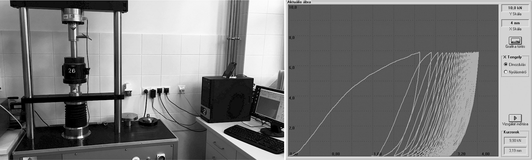
Fig. 5 Cyclic CBR test equipment (a) and force-displacement test chart (b)
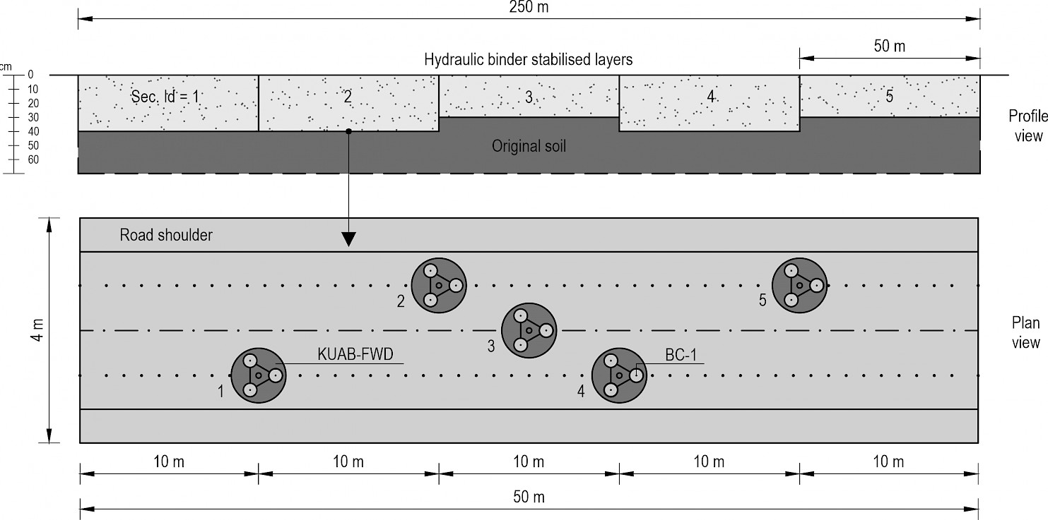
Fig. 6 Schematic diagram of measurement locations and points for dynamic load tests
2.4 Field Tests
2.4.1 Experimental Road Section
In addition to preliminary studies, a 250 metre-long experimental road was built on the site. Based on the laboratory tests, five different 50-metre stabilised sections were built:
3% lime at 40 cm thickness
6% lime-cement mixture at 40 cm thickness
6% lime-cement mixture at 30 cm thickness
6% lime at 40 cm thickness
6% lime at 30 cm thickness
A 70–30% ratio was used for the lime-cement mixtures. The sections were built to 4 metre width. A Wirtgen WR 2400 remixer mounded the soil and mixed the binders. The aim was to determine the variation in the bearing capacity of the subgrade due to the stabilisation of the pilot pavement structures. Therefore, the bearing capacity of the subgrade was measured with a BC-1 (LWD, Light Weight Deflectometer) type hand-held falling weight device before the subgrade stabilisation. It is important to know the water content of the soil to stabilise the top 30–40 cm subgrade layer with binder. Hence, based on laboratory tests, soil samples were taken from the subgrade soil at depths of 10–15 and 30–40 cm. The thickness and water content of the five sections were checked by hand drilling after construction. Finally, the bearing capacity of the finished stabilised subgrade was recorded using BC-1 and KUAB-FWD (Falling Weight Deflectometer) equipment three days after construction, in immediate succession. The location of the measurement sites was the same for all five sections (Fig. 6). Five measurement sites were established for each section with a geometry that allowed the towed KUAB-FWD measuring equipment to be positioned at the set points. The BC-1 device was preloaded with three drops at each measurement location, followed by three measurement drops resulting in a total of 5×3=15 measurements per road section. For the KUAB-FWD, on the other hand, only one preload and one measurement load was applied, which resulted in five measurements per section.
2.4.2 KUAB-FWD Equipment
The KUAB-type FWD equipment (Fig. 7a), which operates by pulse, drops a given mass from a given height to a 30 cm diameter plate with a buffer, using the energy of the position. The loading plate is segmented and divided into four equal parts to provide the best possible fit for the current pavement deformations. During loading, geophones measure the deflection with micrometre precision below the loading plate and 200, 300, 450, 600, 900, and 1200 mm from it along the vehicle axis, thus producing the so-called deflection basin. At least two drops are performed at each measuring point during the measurement, the first of which is a conditioning drop. The equipment records both drops, but only the second drop is used for calculations. The characteristic bearing capacity of the investigated structure is the so-called equivalent surface modulus, which is calculated according to the well-known Boussinesq approximation using Eq. (4).
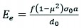 (4)
(4)
Where:
Ee equivalent surface modulus, MPa
f correction factor, value depends on assumed distribution of load force, -
µ Poisson's ratio, -
σ0 load stress, kPa
a radius of loading plate, mm
d0 deflection under loading plate, mm.
Since the KUAB plate is segmented, a correction factor of f=2 was applied, assuming a uniform stress distribution typical of flexible plates. In addition to the measurement results of the falling weight deflectometer with the data of the pavement structure (type and thickness of the layers), a backcalculation procedure can be applied to calculate the load-bearing modulus of the pavement structure layers from the measurement data. The backcalculation-based methods generally use mechanical calculation methods developed for multi-layer pavement structures, starting from known data, and iteratively determining the pavement structure characteristics that best approximate the measured deflection basin (Fig. 7b). PAVBACK v6 software was chosen to process the measured deflection data because of its ability to calculate layer moduli and layer thicknesses or a combination of both.
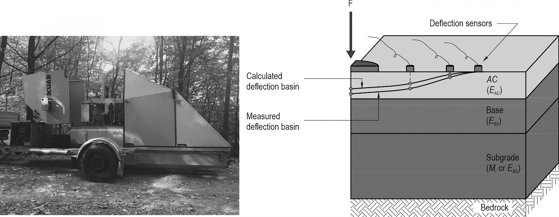
Fig. 7 KUAB-FWD equipment (a) and (b) matching measured and calculated deflection basins (adapted from EVERSERIES 2005)
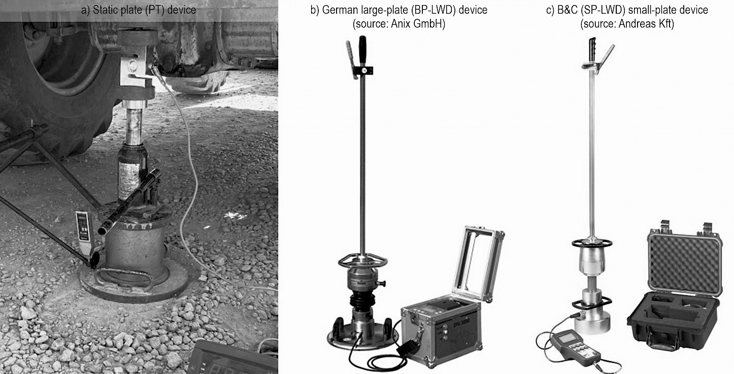
Fig. 8 Plate load test devices
2.4.3 BC-1 (LWD) Equipment
As shown in Fig. 8, in Hungary, static and dynamic plate load test devices are used to assess the bearing capacity of subgrade. The latter is also typically referred to as light falling weight measurement. Therefore, in addition to the KUAB-FWD device, a BC-1 type small-plate (Ø163 mm) deflection testing device was used, which records the maximum vertical displacement d0 under the action of a falling weight of 10 kg. The advantage of this device is that it can be used to collect bearing capacity data quickly and in large numbers. From the measured vertical displacement, the required modulus value is also calculated using Eq. (4), with the difference that the correction factor f=π/2 corresponding to the rigid plate is now applied. The range of dynamic modulus measured with the small-plate BC-1 equipment agrees with the static plate (PT) test results. It differs when the dynamic effect can be applied to the granular material, and its grains can be displaced.
3. Results and Discussion
The cyclic loading of the specimens resulted in a force-displacement chart (Fig. 5b), as per the literature (Opiyo 1995). The example shows that the material under test suffered a permanent deformation of about 3 mm and an elastic deformation u=0.5 mm at the end of Cycle 50.
Table 2 lists the CBR% measured during the experiment and the Mr values calculated using relations (1) and (2). The statistical metrics of the laboratory data reported in Table 2 are not interpreted for each experimental configuration, but for the soil tested. The CBR% values of the samples varied from 13 to 70%, with an average CBR value of 46.5% and a standard deviation of 14.4%. The average of the resilient moduli calculated by the Opiyo formula was 40 MPa (standard deviation: 11.1 MPa), while the average of those calculated by the Molenaar formula was 140.5 MPa (standard deviation: 38.8 MPa). When examining the Mr values calculated from the elastic deformation, the close correlation between the two datasets is striking, but the Molenaar formula gives a value three times higher than the original Opiyo formula. The two correlations were developed for different soils and mould sizes, which may explain the disparate results.
Table 2 CBR values of soil mixtures and resilient moduli calculated using Opiyo and Molenaar formulae (w% = water content after 28 days m/m %)
|
No. |
Binder type |
Nom. |
Binder dose, % |
w, % |
u, mm |
F2.5, kN |
CBR2.5, % |
Mr (Opiyo), MPa |
Mr (Molenaar), MPa |
|
01 |
Lime 100% |
LL |
3 |
13.3 |
0.27 |
4.61 |
34.9 |
35.6 |
124.6 |
|
02 |
LL |
3 |
16.5 |
0.58 |
6.01 |
45.5 |
41.1 |
142.5 |
|
|
03 |
LL |
3 |
19.3 |
0.37 |
5.92 |
44.8 |
36.9 |
128.8 |
|
|
04 |
LL |
5 |
13.8 |
0.24 |
4.70 |
35.6 |
32.7 |
115.6 |
|
|
05 |
LL |
5 |
16.6 |
0.19 |
5.06 |
38.3 |
36.6 |
127.9 |
|
|
06 |
LL |
5 |
19.1 |
0.33 |
5.84 |
44.2 |
32.2 |
114.1 |
|
|
07 |
LL |
7 |
12.7 |
0.16 |
2.79 |
21.1 |
26.2 |
95.50 |
|
|
08 |
LL |
7 |
16.0 |
0.38 |
5.89 |
44.6 |
35.2 |
123.4 |
|
|
09 |
LL |
7 |
19.6 |
0.31 |
6.06 |
45.9 |
37.4 |
130.4 |
|
|
10 |
Lime 70% + cement 30% |
LC |
3 |
10.0 |
0.50 |
4.75 |
36.0 |
32.1 |
117.5 |
|
11 |
LC |
3 |
12.8 |
0.64 |
7.91 |
59.9 |
42.9 |
152.3 |
|
|
12 |
LC |
3 |
15.3 |
0.77 |
7.66 |
58.1 |
34.6 |
122.4 |
|
|
13 |
LC |
5 |
8.90 |
0.57 |
5.51 |
41.7 |
33.5 |
119.2 |
|
|
14 |
LC |
5 |
12.0 |
0.48 |
7.43 |
56.3 |
53.7 |
191.4 |
|
|
15 |
LC |
5 |
14.0 |
0.62 |
8.72 |
66.1 |
48.8 |
173.4 |
|
|
16 |
LC |
7 |
7.90 |
0.54 |
5.19 |
39.3 |
33.3 |
118.6 |
|
|
17 |
LC |
7 |
10.3 |
0.51 |
8.35 |
63.3 |
56.9 |
202.4 |
|
|
18 |
LC |
7 |
12.5 |
0.51 |
9.50 |
72.0 |
64.7 |
230.0 |
|
|
19 |
Lime 70% + cement 30% |
LC |
3 |
17.8 |
0.58 |
7.17 |
54.3 |
42.9 |
152.4 |
|
20 |
LC |
3 |
20.7 |
0.56 |
6.57 |
49.8 |
40.7 |
144.8 |
|
|
21 |
LC |
5 |
18.8 |
0.56 |
8.64 |
65.4 |
53.5 |
190.3 |
|
|
22 |
LC |
5 |
21.4 |
0.50 |
3.93 |
29.8 |
27.3 |
97.20 |
|
|
23 |
LC |
7 |
20.1 |
0.51 |
7.36 |
55.8 |
50.1 |
178.4 |
|
|
24 |
LC |
7 |
22.7 |
0.41 |
1.80 |
13.6 |
14.1 |
56.60 |
When designing the laboratory experiment, it was assumed that the stabilisation bearing capacity depends on the type of binder, binder dosage, and water content of the soil. Data analysis revealed that the binder dosage only slightly affects the average CBR% and Mr values of the samples. In contrast, the water content of the soil seems to have a greater effect on the bearing capacity than the amount of binder. This is in agreement with the results of Lu et al. (2020), who stated that moisture content has the most significant effect on the dynamic resilient modulus of lime-treated expansive soil. As moisture content increases, the dynamic modulus of elasticity decreases significantly.
This effect of water content becomes evident by plotting the CBR% versus moisture content (w%) (Fig. 9). The maximum bearing capacity was achieved at w=15% for the lime-cement mixture, and at w=18% for lime. This water content was close to the optimum compaction water content of the untreated soil (15.8%). Lime binder specifically reduces the bearing capacity of treated soil below w=15% moisture content. The reason is that the lime additive dries the soil first, so the chemical bonds cannot form later due to reduced moisture content. The resulting loose, granular material has less internal cohesion than untreated material. With lime stabilisation, there is only a 3% difference between the w% values for the maximum CBR% bearing capacity (18%) and the limit of the reduction in load bearing capacity (15%).
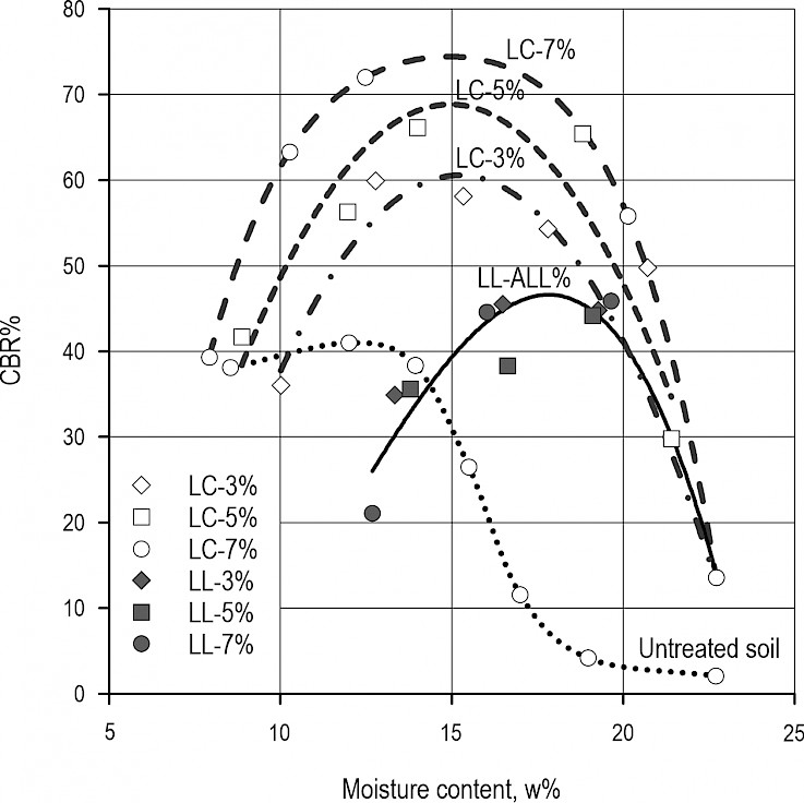
Fig. 9 CBR% values of samples as a function of moisture content w%
The effect of binder amount on the load-bearing capacity could only be clearly demonstrated for lime-cement mixtures. The fitted parabolic curves on the data series show the trend of the load bearing capacity variation. The trend lines converge at 22–23% moisture content, which means that the type and amount of binder no longer play a key role in the achievable bearing capacity. Nevertheless, the treated samples still show a significant additional CBR% (~15%) compared to the untreated soil (~3%).
The series of experiments also aimed to investigate a potential correlation between CBR and the value of the resilient modulus. Using the relationships presented in Table 1, the estimated resilient modulus values were calculated from the measured CBR% data. It was found that the results of the formulae exhibit a significant variance. Compared to the Opiyo formula, the calculated resilient moduli from CBR% are at least three times larger. In contrast, there was a conversion formula that showed agreement with the Mr values calculated with the Molennar formula. The model of Uzan (1985) was the closest to the 45° line (Table 1). Based on the measured data, the result of the Mr values calculated with the Molennar formula would have to be multiplied by 0.28, as shown in Fig. 10, to obtain the resilient modulus value determined by the Opiyo formula in the present experiment. However, this modification should not be applied until the results obtained from the Opiyo formula have been verified.
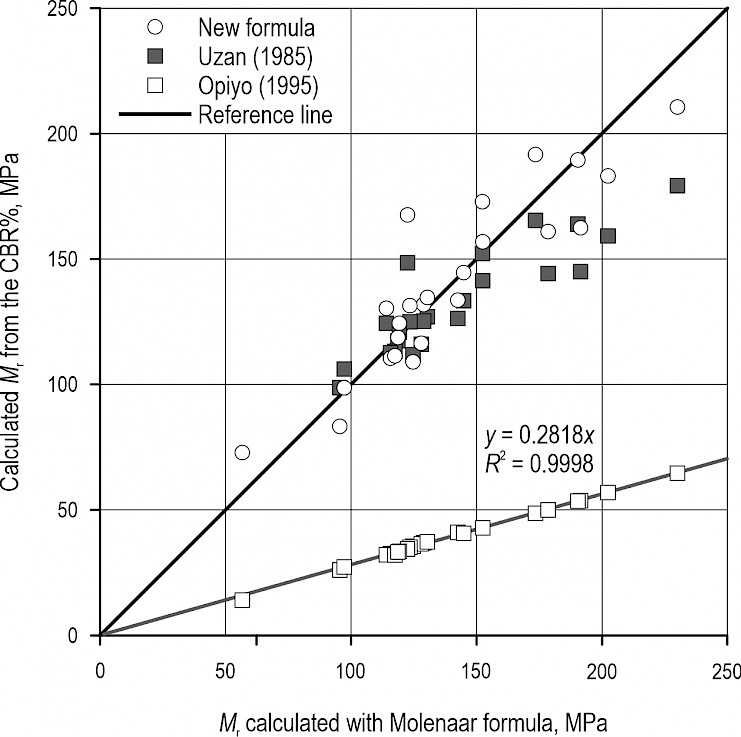
Fig. 10 Mr calculated from CBR% vs Mr calculated with Opiyo formula
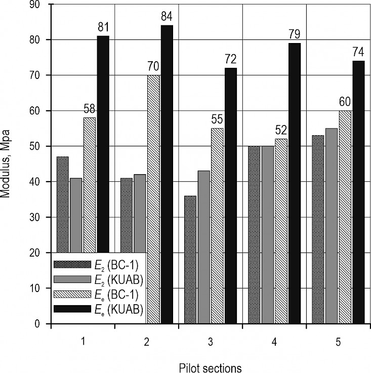
Fig. 11 Average modulus values of stabilisation pilot sections
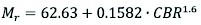 (5)
(5)
The empirical model (5) can be applied to soil stabilisation between 13–70 CBR% when it is not possible to perform a cyclic CBR test.
Field measured bearing capacity data was used to verify the lab results. Based on BC-1 type measurements on the untreated subgrade, it was found that the measured E values were adequate for the bearing capacity required to construct the pavement structure (~40–50 MPa). Water content of the subgrade soil was 28%, which was nearly 5% above the water content of the plastic limit. After soil treatment, the water content of samples taken from 10–15 cm and 30–40 cm depths decreased to 15–17% closer to the surface, and it decreased to 18–22% in deeper parts. The slaking of the ground quicklime and aeration of the soil when the binder was mixed in caused the reduction in water content. The stabilisation of the upper 30–40 cm layer of the subgrade with binder due to the reduced water content creates more favourable conditions for compactibility, which is expected to result in higher bearing capacity.
Table 3 Elastic modulus calculated from laboratory results and field bearing capacity measurements for each stabilisation test section
|
Sec. ID |
KUAB, MPa |
BC-1, MPa |
Laboratory, MPa |
|||||
|
Ee |
E1 |
E2 |
Ee |
E2 |
Mr |
Nom. |
B% |
|
|
1 |
81 |
127 |
41 |
58 |
47 |
128 |
LL |
3 |
|
2 |
84 |
118 |
42 |
70 |
41 |
122 |
LC |
6 |
|
3 |
72 |
120 |
43 |
55 |
36 |
122 |
LC |
6 |
|
4 |
79 |
125 |
50 |
52 |
50 |
118 |
LL |
6 |
|
5 |
74 |
119 |
55 |
60 |
53 |
118 |
LL |
6 |
Fig.11 summarises the bearing capacity data for the untreated and stabilised subgrades in each test section. No measurements were made with the KUAB equipment on the untreated subgrades, only on top of the finished stabilisations. Therefore, the original bearing capacity of the subgrade was recalculated from the deflections. It is evident that the measured BC-1 bearing capacity values on the top of the untreated subgrades are well approximated by the KUAB backcalculated E1 results. A larger discrepancy is only found in the equivalent surface modulus Ee determined at the top of the finished stabilised subgrade. On average, the KUAB device showed a 30% higher bearing capacity value than the BC-1 device. One explanation for this is that the BC-1 has a plate diameter of only 163 mm, while the KUAB-FWD uses a 300 mm plate. The effective depth of the measuring devices is approximately twice the plate diameter. Another reason is that the BC-1 device works with a dynamic load under plate σ0=0.35 MPa, while the KUAB-FWD works with a dynamic load under plate σ0=0.70 MPa. The largest increase in bearing capacity was shown in test section 2, where a 6% lime-cement stabilisation was constructed at a thickness of 40 cm.
From the deflection data recorded with KUAB-FWD, the untreated subgrade and the stabilised layer modulus for all test sections were calculated. From the Mr resilient modulus values measured in the laboratory, the expected bearing capacity values for each test section were calculated by interpolation as a function of binder dosage (B%) and moisture content (w%). The field moisture content was assumed to be w=20% on average based on the samples collected. Table 3 reports the results. According to the table, the calculated E2 modulus values of the sections and the laboratory-determined Mr resilient modulus of stabilisation are in order of magnitude. Based on the E2 values, the largest increase in bearing capacity was observed in test section 1, where a 3% lime stabilisation was built at a thickness of 40 cm. Unfortunately, due to the high moisture content and low curing time, no differences could be detected between the mixtures, and thus between the test sections, based on the type and amount of binder. However, the effect of the thickness of the stabilised layers, albeit small, was visible in the results. Based on the data, the test sections (1, 2 and 4) constructed with a 40 cm thick stabilisation showed the highest increase in bearing capacity.
Von Quintus and Killingsworth (1997), in their research report, proposed a seed modulus of 140 MPa for the lime-stabilised and 350 MPa for the cement-stabilised soil layer for FWD back calculation method. Qubain et al. (2000) proposed a value of 165 MPa for the resilient modulus of the lime stabilized layer. The authors of the present study, based on their previous road experiment, calculated the modulus of the lime-stabilised layer of 500 MPa in a strongly cohesive clay soil (Péterfalvi et al. 2015). AUSTROADS recommends that the modulus of the modified subgrade should be between 20–280 MPa (Bartley Consultants Ltd. 1998), while the Queensland State Design Guidelines require a design modulus of 210 MPa for a lime-stabilised subgrade (Queensland Government 2021). Therefore, it can be concluded that the values of resilient modulus presented in this paper are similar to those published in the field, even if they are largely determined by the properties of stabilised soil.
Based on the field measurements, it was concluded that the Mr values calculated with the Molenaar formula provide a good estimate of the expected bearing capacity of the stabilisation layers. However, the load bearing capacity of stabilisation structures varies continuously over time. Thus, long-term observations are needed to verify these conclusions. In any case, the following design process can be proposed based on the experience gained so far:
Identification of the untreated subgrade soil
Determining the target water content (wsg%) of the untreated subgrade
Determining the type and dosage (B%) of binder
Calculating the design water content: wlab% = wsg% + B%
Preparing the stabilisation test specimen in a CBR mould on wlab%
Performing cyclic CBR test after 28 days of rest
Calculating the resilient modulus based on Eq. (3).
In cases where it is not possible to perform a cyclic CBR test, it appears to be appropriate to estimate the Mr value from the CBR% for a 2.5 mm penetration using Uzan's (1985) equation.
4. Conclusions
The results show that, at the time of preparation, water content affected the load-bearing capacity of the soil stabilisation tested more than the binder dosage. In addition, the optimum water content could be determined where the CBR and Mr were the highest. Some of the experiments do not allow for long-term conclusions, but the results suggest that keeping the water content of the soil at the optimum level is a more important consideration for load-bearing capacity than the exact binder dosage when preparing soil stabilisation.
The cyclic CBR test appears to be a promising method to determine the elastic behaviour of different types of stabilisation. The test can be easily performed with existing CBR testing equipment, and the results can be used to calculate the resilient modulus. The calculated resilient modulus values from the results of the cyclic CBR test were found to be in the order of magnitude as expected, and the calculated modulus values varied more or less regularly with the variation of the mixture properties. Molenaar's Eq. (3) gave results of the same order of magnitude as the CBR-Mr conversion formulae found in the literature. It is advisable to perform dynamic triaxial testing of the mixtures to select the more useful one among the presented calculations and possibly to prescribe a model that is more accurate than the previous ones.
In line with previous experience, the bearing capacity measurements on the pilot pavement sections constructed clearly demonstrated that weather-independent transportation on dirt roads with cohesive and intermediate soils can be greatly improved with soil stabilisation using different binders. These binders provide adequate support for the thin, well-graded, crushed stone pavement layers built on a soil stabilisation pavement base. As a comparison, the experimental pavement sections should be complemented in the future with structures using geotextile, geogrid and crushed stone or sandy gravel and crushed stone as subgrade. After the construction of the pilot sections, the changes in conditions due to traffic will be monitored by determining the load-bearing capacity and surface deformation. To this end, the traffic volume will be monitored and, depending on that volume, bearing capacity measurements will be performed twice a year or at least annually.
Acknowledgments
Egererdő cPlc. financed the construction of the experimental pavement sections presented in the study. Carmeuse Hungária Ltd. provided the binder for the laboratory tests. This article was made in frame of the project TKP2021-NKTA-43, which has been implemented with the support provided by the Ministry of Innovation and Technology of Hungary (successor: Ministry of Culture and Innovation of Hungary) from the National Research, Development and Innovation Fund, financed under the TKP2021-NKTA funding scheme.
5. References
Åhnberg, H., Johansson, S.-E., Pihl, H., Carlsson, T., 2003: Stabilising Effects of Different Binders in Some Swedish Soils. Proceedings of the Institution of Civil Engineers – Ground Improvement 7 (1): 9–23. https://doi.org/10.1680/grim.2003.7.1.9
Bartley Consultants Ltd. 1998: Design of Pavements Incorporating a Stabilised Subgrade Layer: Literature Review. Research Report 104. Auckland, NZ, Transfund New Zealand.
Green, J.L., Hall, J.W., 1975: Nondestructive Vibratory Testing of Airport Pavements. Vicksburg, Miss.: Waterways Experiment Station.
Heukelom, W., Klomp, A.J.G., 1962: Dynamic Testing as a Means of Controlling Pavements During and After Construction. In International Conference on the Structural Design of Asphalt Pavements. University of Michigan, Ann Arbor. 203: 495–510.
Hopkins, T., 1994: Minimum bearing strength of soil subgrades required to construct flexible pavements. In Proceedings of the 4th International Conference, Bearing Capacity of Roads and Airfields. Minneapolis, MN, USA: Minnesota Department of Transportation 605–617.
Kenya Road Design Manual. 1987: Road Design Manual, Part III: Materials and Pavements Design for New Roads. Nairobi, Kenya: Ministry of Transportation and Communications.
Lu, Z., Zhao, Y., Xian, S., Yao, H., 2020: Experimental Study on Dynamic Resilient Modulus of Lime-Treated Expansive Soil. Advances in Materials Science and Engineering 2020: 1–10. https://doi.org/10.1155/2020/3272681
Mukabi, J.N., 2016: Review of DCP Based CBR UCS and Resilient Modulus Models for Applications in Highway and Airport Pavement Design. Academia.Edu E-Publication Pre-Print.
Ohio DOT. 2008: Pavement Design Manual. Colombus, Ohio, USA: The Ohio Department of Transportation, Office of Pavement Engineering.
Opiyo, T.O., 1995: A Mechanistic Approach to Laterite-Based Pavements. M.Sc thesis, Delft: International Institute for Infrastructural, Hydraulic and Environmental Engineering.
Paterson, W.D.L., Maree, J.H., 1978: An Interim Mechanistic Procedure for the Structural Design Pavements. Pretoria, South Africa: National Institute for Transport and Road Research.
Péterfalvi, J., Primusz, P., Markó, G., Kisfaludi, B., Kosztka, M., 2015: Evaluation of the Effect of Lime-Stabilized Subgrade on the Performance of an Experimental Road Pavement. Croatian Journal of Forest Engineering 36 (2): 269–82.
Powell, W.D., Potter, J.F., Mayhew, H.C., Nunn, M.E., 1984: The Structural Design of Bituminous Roads. LR1132. Crowthorne, Berkshire, UK, TRRL.
Qubain, B.S., Seksinsky, E.J., Li,J., 2000: Incorporating Subgrade Lime Stabilization into Pavement Design. Transportation Research Record: Journal of the Transportation Research Board 1721 (1): 3–8. https://doi.org/10.3141/1721-01
Queensland Government. 2021: Structural Design Procedure for Lime Stabilised Subgrade. Guideline. The State of Queensland: Department of Transport and Main Roads.
Ševelová, L., Florian, A., Žák, J., 2021: Influence of Plunger Stress on Resilient Modulus of Forest Subgrade Soils Obtained from Cyclic CBR Test. Forests 12 (11): 1456. https://doi.org/10.3390/f12111456
Sirivitmaitrie, C., Puppala, A. J., Saride, S., Hoyos, L., 2011: Combined Lime–Cement Stabilization for Longer Life of Low-Volume Roads. Transportation Research Record: Journal of the Transportation Research Board 2204(1): 140–47. https://doi.org/10.3141/2204-18
Solanki, P., Zaman, M.M., Dean, J., 2010: Resilient Modulus of Clay Subgrades Stabilized with Lime, Class C Fly Ash, and Cement Kiln Dust for Pavement Design. Transportation Research Record: Journal of the Transportation Research Board 2186 (1): 101–10. https://doi.org/10.3141/2186-11
Szendefy, J., 2017: Bearing Capacity and Durability of Stabilized Soils with HRB. In Proceedings of 19th International Conference On Soil Mechanics and Geotechnical Engineering, 1415–1418.
Uzan, J., 1985: Characterization of Granular Material. Transportation Research Record 1022(1): 52–59.
Von Quintus, H.L., Killingsworth, B., 1997: Design Pamphlet for the Backcalculation of Pavement Layer Moduli in Support of the 1993 AASHTO Guide for the Design of Pavement Structures. Final Report FHW A-RD-97-076. United States. Federal Highway Administration, office of Engineering.
Webb, W.M., Campbell, B.E., 1986: Preliminary Investigation into Resilient Modulus Testing for New AASHTO Pavement Design Guide. Atlanta, GA, USA: Office of Materials and Research, Georgia Department of Transportation.
Washington State Department of Transportation, 2005: EVERSERIES© User's Guide: Pavement Analysis Computer Software and Case Studies. Washington State Department of Transportation, Olympia, WA, USA.
Hao, S., Pabst, T., 2021: Estimation of resilient behavior of crushed waste rocks using repeated load CBR tests. Transportation Geotechnics 28: 100525. https://doi.org/10.1016/j.trgeo.2021.100525
Robinson, R.G., Krishnan, J.M., 2016: Use of repeated load CBR test to characterize pavement granular materials. In: Functional Pavement Design – Proceedings of the 4th Chinese-European Workshop on Functional Pavement Design, CEW 2016, 965–976.
© 2023 by the authors. Submitted for possible open access publication under the
terms and conditions of the Creative Commons Attribution (CC BY) license (http://creativecommons.org/licenses/by/4.0/).
Authors' addresses:
Assist. prof. Péter Primusz, PhD *
e-mail: primusz.peter@uni-sopron.hu
Assist. prof. Balázs Kisfaludi, PhD
e-mail: kisfaludi.balazs@uni-sopron.hu
Asocc. prof. József Péterfalvi, PhD
e-mail: peterfalvi.jozsef@uni-sopron.hu
University of Sopron
Faculty of Forestry
Institute of Geomatics and Civil Engineering
Bajcsy-Zsilinszky u. 4.
H-9400, Sopron
HUNGARY
* Corresponding author
Received: September 17, 2022
Accepted: March 21, 2023
Original scientific paper