Power Curve Determination and Electrification of Powertrain System of Harvester Crane Swinging
doi: 10.5552/crojfe.2024.2342
volume: 45, issue: 2
pp: 12
- Author(s):
-
- Mergl Václav
- Procházka Petr
- Nagy Miroslav
- Ziezinger Lukáš
- Vítek Ondřej
- Gulan Ladislav
- Article category:
- Original scientific paper
- Keywords:
- CTL (Cut to length) technology, electric motor, crane swing, recuperation, emissions, power curve
Abstract
HTML
The work deals with the determination of the power curve for driving the swinging of the hydraulic crane of the harvester and the subsequent replacement of the hydraulic motor with an electric motor for the possibility of recuperating braking energy. For this purpose, the hydraulic circuit of the crane slewing gear was measured with flowmeters during its rotation between the angles –105° to +105°, –90° to +90° and –36° to +22°. The power was calculated from the measured values. The maximum power needed to swing the harvester crane was 9720 W. With this power, the torque reached 187.98 Nm. The average value of the power needed to swing the hydraulic crane was only 2472 W at a torque of 47.81 Nm. From these values, a synchronous electric motor with permanent magnets with a nominal speed of 2000 rpm (rotation per minute) and a power of 3246 W emerged as suitable for replacing the hydraulic motor. The use of an electric motor would, however, require a planetary gearbox with fast input speeds that would then be reduced to slow output speeds. The research results demonstrated the possibility of using an electric motor to swing the hydraulic crane during the work cycle of the harvester for the use of energy recovery from crane braking and thus the possibility of reducing fuel consumption and emissions.
Power Curve Determination and Electrification of Powertrain System of Harvester Crane Swinging
Václav Mergl, Petr Procházka, Miroslav Nagy, Lukáš Ziezinger, Ondřej Vítek, Ladislav Gulan
Abstract
The work deals with the determination of the power curve for driving the swinging of the hydraulic crane of the harvester and the subsequent replacement of the hydraulic motor with an electric motor for the possibility of recuperating braking energy. For this purpose, the hydraulic circuit of the crane slewing gear was measured with flowmeters during its rotation between the angles –105° to +105°, –90° to +90° and –36° to +22°. The power was calculated from the measured values. The maximum power needed to swing the harvester crane was 9720 W. With this power, the torque reached 187.98 Nm. The average value of the power needed to swing the hydraulic crane was only 2472 W at a torque of 47.81 Nm. From these values, a synchronous electric motor with permanent magnets with a nominal speed of 2000 rpm (rotation per minute) and a power of 3246 W emerged as suitable for replacing the hydraulic motor. The use of an electric motor would, however, require a planetary gearbox with fast input speeds that would then be reduced to slow output speeds. The research results demonstrated the possibility of using an electric motor to swing the hydraulic crane during the work cycle of the harvester for the use of energy recovery from crane braking and thus the possibility of reducing fuel consumption and emissions.
Keywords: CTL (Cut to length) technology, electric motor, crane swing, recuperation, emissions, power curve
1. Introduction
Currently, there is concern about the availability of fossil fuels and the damage caused by emissions, which include carbon monoxide (CO), carbon dioxide (CO2) and nitrogen oxides (NOX) along with particulate matter (PM). As a result, regulations aimed at gradual reduction of emission have been introduced (Wasilewski et al. 2020, Di Blasio et al. 2022, Mizik 2022). Reduction of emissions can be achieved by several methods. The first one uses already well-known conventional filters that can be found on the exhaust system of the machine (Sejkorová et al. 2017, Hurtová et al. 2019). The second method for limiting the production of emissions is to use alternative fuels with a lower content of undesirable substances, which could also help to replace fossil fuels to a certain extent. Those alternative fuels include liquefied petroleum gas (LPG) (Fabiś and Flekiewicz 2021), compressed natural gas (CNG) (Khan et al. 2015) or its liquefied form (LNG) (Langshaw 2020). However, the results of research on fossil fuels of the diesel fraction group show that this type of fuel could also be a viable alternative (Labaj and Barta 2006, Górski et al. 2018, Hissa et al. 2019, Rayapureddy et al. 2022, Hunicz et al. 2022). A possible alternative is an energy source that does not consume fossil fuels, but uses renewable sources such as solar energy (Małek et al. 2022). The last option for reducing emissions and fuel consumption is the hybridization of machine powertrain systems.
In the forestry sector, due to the widespread use of diesel engines, the main way to reduce emissions is hybridization (with filters on the exhaust system). This method also helps to reduce fuel consumption, which accounts for 82% of the total costs of felling when using CTL (Cut to Length) technology (Klvač et al. 2003). According to Eniola (2013), the use of hybrid systems could reduce fuel consumption by 25%, while a study by Lajunen et al. (2016) showed that this reduction could range from 10 to 50%. The advantage of hybridization is the reduction of internal combustion engines, which can reduce the overall weight and dimensions of the given machine (Sellgreen 2014). Currently, hybrids in forestry can be divided into hydraulic, electric and electro-hydraulic (not yet commonly used). Electric hybrid systems are the most used in machines for CTL technology and, therefore, will be the main focus of this study.
Nowadays, various electric hybrid powertrain solutions can be found in CTL technology machines. The most commonly used electric hybrid machine is the harvester from Logset Oy. The manufacturer's system includes an electric motor with the possibility of a generative mode, while the electrical energy is modified by a converter and stored in a supercapacitor. The system control unit monitors the load on the diesel engine and quickly intervenes as soon as the rpm starts to decrease (Johnsen 2022). The control unit turns on the electric motor and it immediately adds torque to the hydro-generator. When the engine load is normal, the electric motor switches to the generative mode and charges the supercapacitor (Logset Oy 2022). It takes 9 to 10 seconds for the supercapacitors to charge and discharge (Johnsen 2022). The same system is also used by the manufacturer Elforest Technologies AB in cooperation with Ponsse Plc., whose product is known under the name »Elturbo« (Elforest Technologies AB 2022). However, this company is not only concerned with increasing engine performance but also replacing almost the entire mechanical part of the wheel drive in the conventional powertrain system of the harvester. Specifically, the system in question consists of an internal combustion engine, behind which a generator is located which produces electrical energy that is led through a converter to an electric energy accumulator, from which, through the converter, electrical energy flows to electric motors located on the axles of the machine (Rong-feng et al. 2017). However, solutions with electric motors in wheel hubs can also be found. An example can be the forwarder from the company Elforest Technologies AB, which uses AC electric motors with a power of 30 kW (Stoddart 2010). According to Edlund et al. (2012), this solution helps to decrease the total weight of the machine.
Currently, the EV1 concept of Ponsse Plc. and Epec has also appeared on the market (Ponsse Plc. 2022, Jonsson 2022a). This concept includes the same principle as with the previous manufacturers, but the internal combustion engine of the machine is turned off during work and the entire system is powered only by accummulators, which is different from other systems, because in their cases the internal combustion engine runs continuously in order to recharge the batteries. In the EV1, the internal combustion engine (150 kW) operates for only 50% of the machine working cycle, coupled with a 100 kW generator (Haugh 2022, Robert Easton Ltd. 2022). It takes 15 to 20 minutes to charge the accumulators by 31.5 kW/h, while the machine can work for 30 to 45 minutes without burning fossil fuel. Accumulators are charged while the machine is working. Furthermore, the concept of the manufacturer Malwa Forest AB and their modification of the powertrain of the dual machine 560 C was also presented. This machine was fully electrified (Elmia AB 2022). The diesel engine was replaced by two electric motors powered by accumulators, one electric motor being intended for driving the crane and the harvester head, and the other for driving the traction device (Jonsson 2022b). Electrical energy is obtained by recharging from the electrical grid, while the accumulators are modular (Engström 2022). Modularity makes it possible to exchange discharged accumulators for newly charged ones. The machine is equipped with two accumulator modules; the larger module is intended for the machine work, while the smaller one is used when replacing the larger module, as the machine crane is used for the replacement. A machine equipped in this way is able to work for 2 hours per charge (module replacement) (Lesprom Network 2022). However, all these systems do not allow to recover energy from the movement of the crane commonly used in CTL technology.
An example of a hybrid solution with energy recovery is the system of Komatsu Ltd used in their excavators. The system works with one supercapacitor and two electric motors with the option of generative mode (Lin et al. 2010). The first electric motor is located between the internal combustion engine and the hydraulic motor on the shaft. This electric motor primarily produces electricity and then relieves the internal combustion engine when it is overloaded. A second electric motor is used instead of the slewing hydraulic motor, while its function (swinging) is preserved. This electric motor primarily swings the superstructure with the crane, while the energy is recovered during braking and stored in a supercapacitor. However, a similar system with accumulators was developed by CNH Industrial, known for its brand New Holland Agriculture (Mergl 2022). This system, with an electric motor intended for swinging, could be a solution to reduce the loss of energy during the harvester work, for which possibilities of obtaining electrical energy rely only on systems of the »Elturbo« type, which can be quite problematic when felling poplar and eucalyptus plantations (high felling intensity with a minimum of interruptions to charge the electrical source). However, several questions arise, such as: What is the course of the power curve when the crane is swinging, or which electric motor of nominal power to use in such a way as to enable the recovery of energy from braking and thereby enable the reduction of emissions or engine downsizing. These questions are addressed in this research.
2. Materials and Methods
2.1 Used Machine
As part of the research, a hybrid thinning harvester AH6 from Agama a.s. was chosen to replace the hydromotor with an electric motor in the slewing gear of the harvester crane. (Fig. 1). This new design of harvester with an electric hybrid powertrain system of the »Elturbo« type with an accumulator has a weight of 7640 kg including fuels and harvester head. With the operator, the total weight is 7740 kg. Turning of the harvester is solved by turning the wheels of the front and rear axles, which are fitted with 500x45 R22.5 tires. Among other things, the machine is capable of »crab walk« or turning only with the help of the front axle. The machine frame is leveled using fixed axles, while the axles are leveled by 4 hydraulic cylinders (1 axle = 2 hydraulic motors). The front axle can tilt by ±10° and the rear by 5° more. The AH6 harvester is equipped with a parallel hydraulic crane in front of the cabin on its platform. The cabin is rotatable, located on a swivel bearing ring, which is leveled in only two directions, i.e. forward and backward. The rotation of the slewing gear itself is within ±105°. The hydraulic crane and its attachment to the supporting platform of the cabin allows vertical swing of the crane to the left or right side by ±20° with the help of two hydraulic cylinders. The maximum reach of the crane is 7 m from the central axis of the slewing gear. The machine is equipped with a 325H harvester head from Nisula Forest Oy with a cut of 340 mm and a weight of 285 kg.
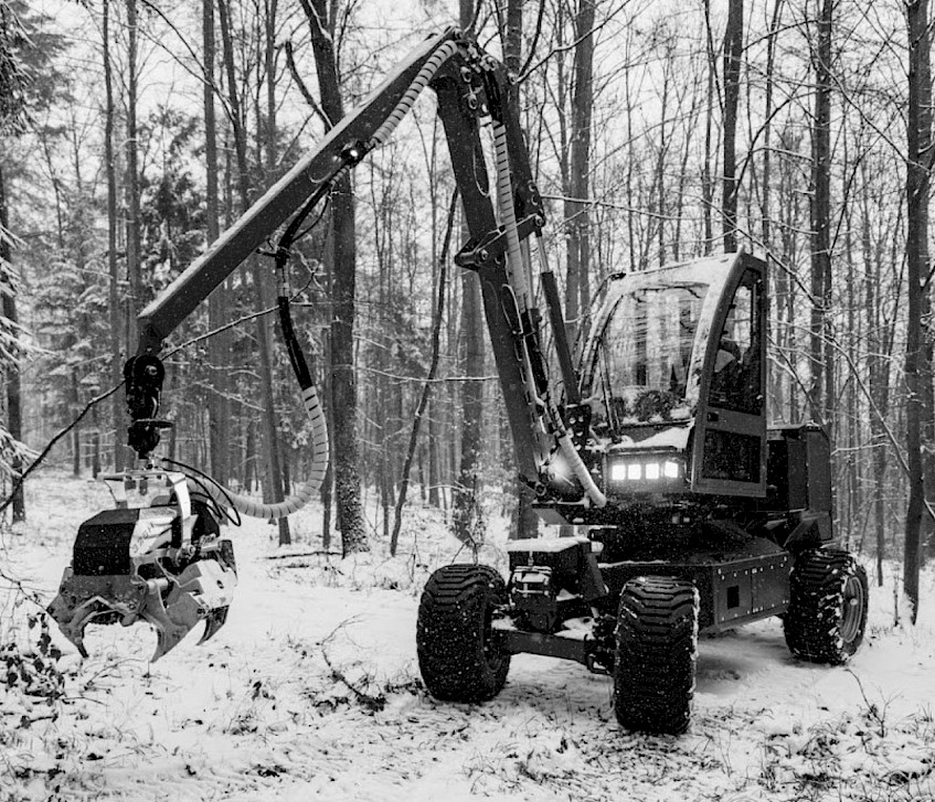
Fig. 1 Harvester AH6 from Agama a.s.
2.2 Measurement of Required Power
Flowmeters were placed in the hydraulic system in order to obtain data for determining the power for swinging the machine crane and subsequently choosing a suitable electric motor. Two HySense QT 100 turbine flowmeters and MultiHandy 3020 data loggers from Hydrotechnik GmbH were used for this purpose. Each flowmeter was equipped with sensors that recorded the flow, pressure and temperature of the hydraulic oil. Specifically, the HT-PD ISDS sensor with the range of 0 to 600 bar was used for pressure monitoring. Furthermore, the flow meter was fitted with an ISDS turbine with a measuring scale of 9 to 300 l/min. According to the manufacturer, Hydrotechnik GmbH, the measurement accuracy of the HySense QT 100 flowmeter equipped in this way is 0.5%. A flowmeter with these parameters made it possible to capture any extreme pressure and flow peaks. The flowmeters were placed between the hydraulic switchboard and the hydraulic motor of the AH6 harvester crane slewing gear (see Fig. 2), which is connected to the planetary gearbox, which enables the change of the transmission ratio to ensure the corresponding swinging speed. The flowmeters placed in this way were subsequently connected to data loggers with a set measurement frequency of 33 Hz. It should be mentioned that the one-way flowmeters had to be protected against deterioration by bypasses with check valves with an overflow pressure of 1 bar, whereby one check valve was placed behind the flowmeter (in the flow direction) and the other was mounted on the bypass branch in the opposite direction.
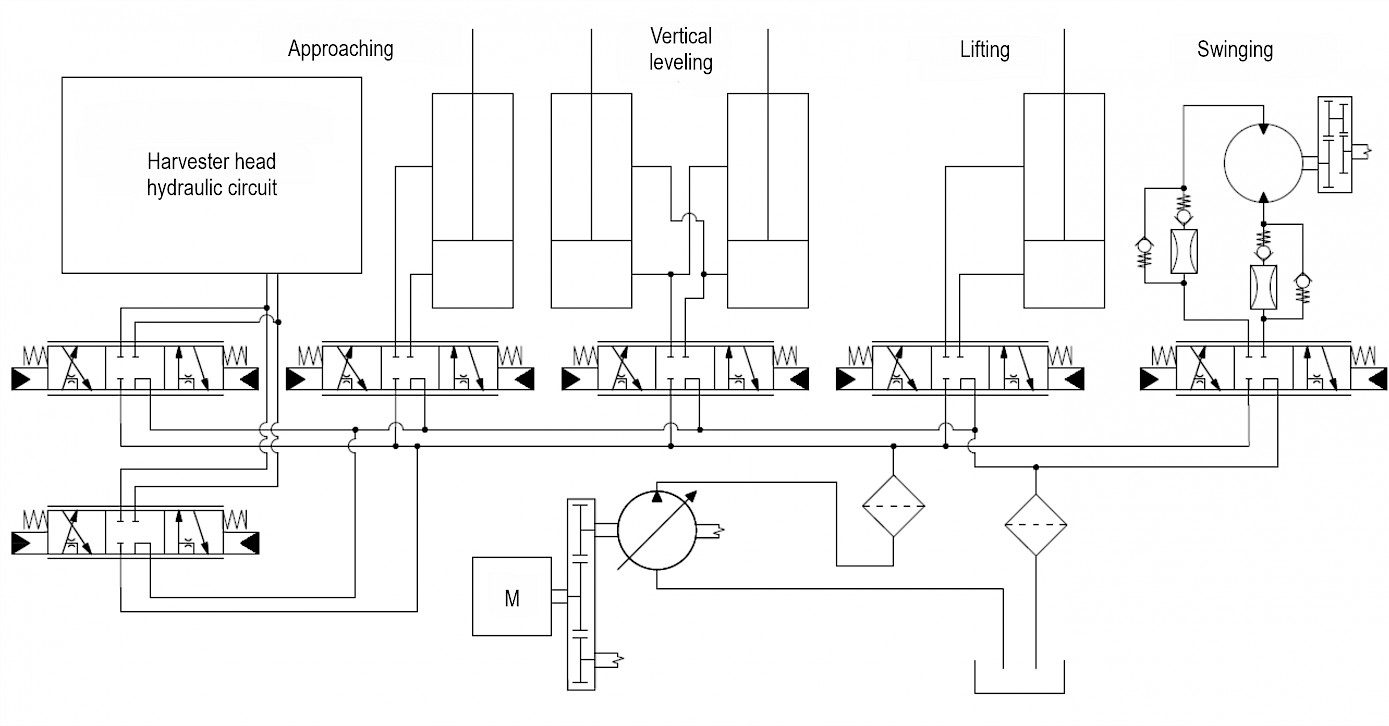
Fig. 2 Location of flowmeters in machine hydraulic circuit
Subsequently, the intput power needed to swing the crane was calculated from the flow and pressure data obtained in this way. The calculation was made according to the following eq. 1:
 (1)
(1)
Where:
P input power, W
Q flow, l/min
P pressure, bar
η hydraulic system efficiency
2.2 Measurement Methodology
The used machine with installed flowmeters in the system was subjected to the following measurement methodology. Several axes were marked throughout the working angle of the slewing gear. The first one was parallel to the longitudinal axis of the machine. The angle in which the axis was located was evaluated as 0°. From this axis, another 6 axes were marked at different angles from the 0° reference axis. The first three axes formed an angle of –105°, –90° and –36° with the 0° axis. The other three axes formed the following angles with the 0° axis: +22°, +90° and +105°. Two points were marked on all axes, the first one at 5.3 m from the center of the slewing bearing and the second one at 7 m, which is the full reach of the AH6 harvester hydralic crane. On the axes with points marked in this way, the following measurements were carried out according to the following rules.
First, the crane was placed on the –105° axis and extended to 7 m, while the crane suspension joint was 177 cm above the ground. After that, the swinging of the crane was started towards the +105° axis, but the movement was interrupted at the 0° axis, so that the harvester head did not oscillate. This stop also occurs in practice, because the operator first needs to make sure, from the safety point of view, that no one has entered the threatened area and also to look around at what he will do at the end point. Among other things, partial processing of the tree takes place in front of the machines. Subsequently, after 2 seconds had passed, the swinging towards the +105° axis was started again, where the crane stopped again in its rotation so that there was no unwanted movement of the head. On the +105° axis, the direction of swinging was thus reversed towards –105° and again the movement was stopped at the 0° axis. Then followed the same procedure as when moving to the +105° axis, but towards the –105° axis. These movements from –105° to +105° and back were considered one measurement cycle, and the cycle was repeated five times in total. After carrying out these cycles, the –90° axis was chosen as the starting and end point of the next measurement (5 more cycles), while the turn was made in the +90° axis, again with stops in the 0° axis. This was also the case with the next measurement, where the start and end points were chosen to be the –36° axis with a turn in the +22° axis and stops in the 0° axis. After that, the reach of the crane was reduced to 5.3 m and everything was repeated exactly as with the maximum reach (7 m). Fig. 3 presents a drawing of the measurement methodology for a better understanding.
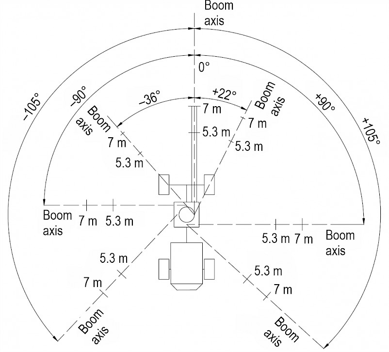
Fig. 3 Measurement methodology
3. Results
3.1 Power Curve
Fig. 4 shows the measured values of the hydraulic system and their course into input of the motor during crane swinging in the range of axes –105° and +105° within the reach of the crane of 5.3 m. During this movement, the highest rotation speed of the crane occurs and therefore there is also a large flow of hydraulic oil, which results in the highest performance according to eq. 1. Specifically, the flow and pressure curve during one defined measurement cycle can be noticed, which reached the highest values within 5.3 m. During the measurement of this crane reach, a maximum pressure of up to 126.42894 bar was recorded (Fig.4). However, the maximum pressure during the entire measurement in the reach of the crane of 5.3 m was 135.36100 bar. During the movement, the pressure reached values ranging from 74.69606 to 113.06219 bar. Fig. 4 shows significant pressure fluctuations during the movement of the crane. In these fluctuations, the pressure reached only 31.21012 bar, while the lowest pressure value in the entire measurement in this range was down to 18.19599 bar. In contrast, the recorded flow rate was relatively balanced and ranged from 27.1502 l/min to 47.7150 l/min. Fig. 4 clearly shows that, after the maximum opening of the hydraulic distributor valve, the flow stabilized considerably and its value was around 40 l/min. Different flow values were achieved when swinging from the –36° axis to the +22° axis and back, where the flow rate was around 30 l/min.
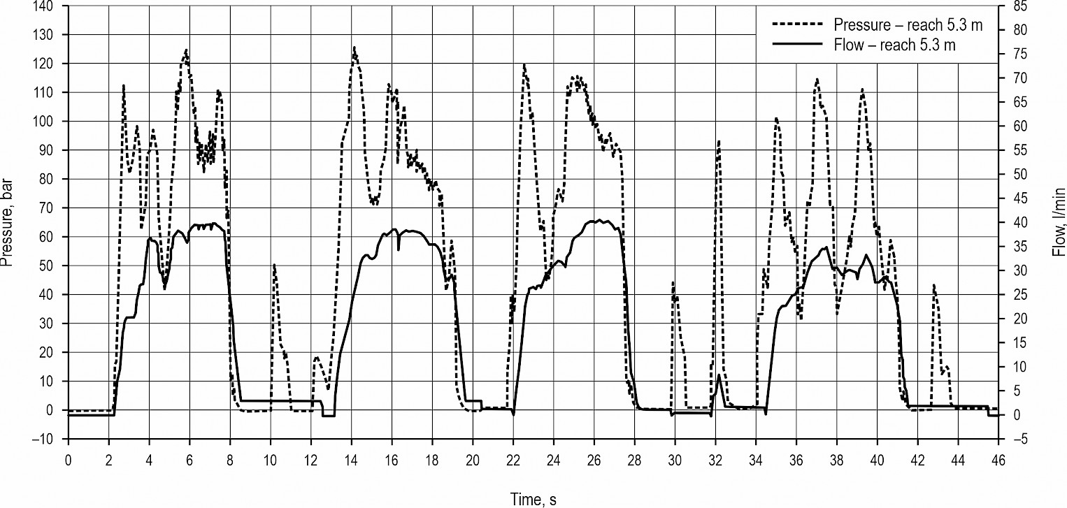
Fig. 4 Pressure and flow into motor input when moving from –150° to +105° and back in 5.3 m
The average behavior of hydraulic oil pressure and flow rate into input of the motor when the crane is swinging in its maximum range (7 m) can be seen in Fig. 5. Specifically, this is the movement of the crane from the –105° axis to the +105° axis and back. This measurement cycle can be considered representative within the scope of repetition in one measurement, while the measurement itself (movement from –105° to +105°) reached the highest values of the flow and therefore the power. Fig. 5 shows the increased pressure every time the crane starts to swing. The pressure during these peaks reached up to 129.77660 bar, with a maximum of 135.15200 bar recorded throughout the measurement. After this peak, a slight drop was recorded, which was 79.90656 bar, but during all measurements within a range of 7 m, a larger drop was also recorded at 38.91120 bar. Subsequently, the pressure rose and ranged from 79.90656 bar to 115.63078 bar. A similar phenomenon with a starting high pressure peak was also recorded during measurements at a range of 7 m (see Fig. 4). Furthermore, Fig. 5 shows a balanced flow during the maximum opening of the distributor valve, as was the case in Fig.4. However, the flow in this case was between 40 and 45 l/min, which was more than when measuring starting at the –36° axis with a turn at the +22° axis. Specifically, a flow rate of around 25 l/min was recorded.
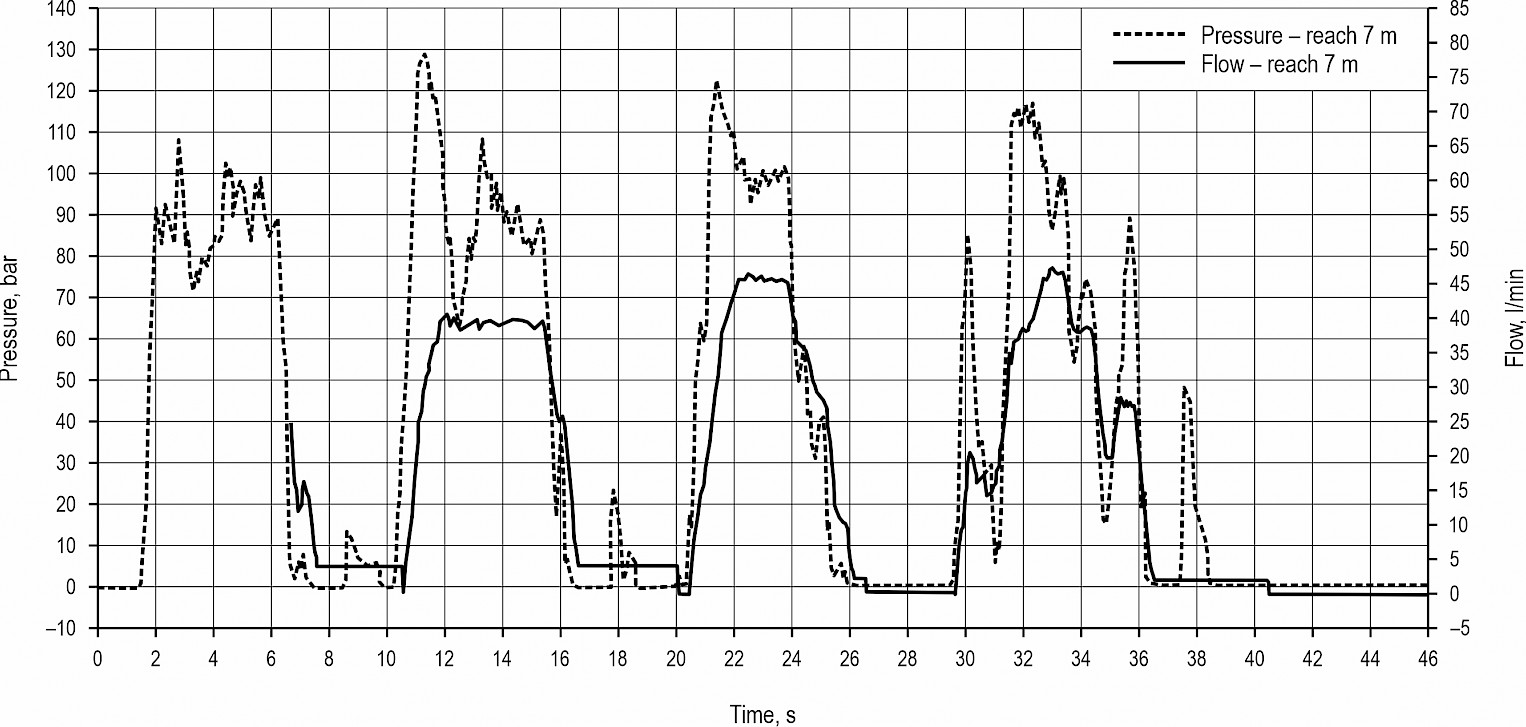
Fig. 5 Pressure and flow into motor input when moving from –150° to +105° and back in 7 m
From the pressure and flow values obtained in this way, the power needed to swing the crane was calculated with the hydraulic system efficiency of 0.85 (η). This efficiency value was taken according to the specification of the hydraulic motor manufacturer and their certification system. Fig. 6 shows the powers within the swinging between the axes –105° and +105° in one cycle at a crane reach of 5.3 m and 7 m. The highest power within the given cycle and the entire measurement was calculated when the crane returned from the +105° axis in a range of 7 m. Its value was 9720 W, which is 593 W more than the 5.3 m range, which was 9127 W. This value was achieved when swinging from the +90° axis to the –90° axis at a crane reach of 5.3 m. The lowest maximum power in the entire measurement was only 3078 W and was achieved when the crane was swinging within a range of 5.3 m from the +22° axis to the –36° axis. With the same movement, but with the crane extended to the maximum, the calculated power was 5545 W. When moving to the left, the power maximum was also recorded for measurements with the start and end points on the –90° axis with a turn on the +90° axis. At a range of 7 m, the power was 9156 W and at 5.3 m it was 9696 W. Fig. 6 aslo shows the possibility of energy recovery with the starting braking of the crane, which can be located at the end of each movement, while its beginning is included at the end of the power peaks. In the current version of the drive, the hydromotor is not capable of recuperation. However, this possibility arises when using an electric motor.

Fig. 6 Input power when swinging from –105° to +105°
3.2 Choice of Electric Motor
Based on the measured results shown in Fig. 6, the most demanding possible work cycle of the electric motor was determined. As shown in Fig. 6, this is intermittent periodic loading, which reaches maximum values of approx. 9 kW. Due to the used planetary gearbox and the ratio of the sprocket and ring of the slewing gear, the total transmission to the motor shaft is 1/86.9. At a given slewing speed of 0.595 rad/s, the motor speed is 494 rpm, which, given the required maximum power of 9720 W, means that the required maximum torque reaches 187.98 Nm. From the above Fig. 6, it is also possible to determine the mean power value, which is equal to 2471 W, with the mean torque value of 47.81 Nm. Therefore, a low-speed electric motor with a high torque on the shaft would be a suitable option. This working area is quite disadvantageous from the point of view of the given application, because the size of the electric motor is proportional to its output torque rather than power. The torque is directly proportional to the magnitude of the phase current and the motor winding has a defined current density. The greater the current flowing through the winding, the larger the cross-section of the conductors must be, and therefore the total volume of the winding also increases, as well as that of the machine. Therefore, a larger gear ratio was chosen so that the engine could be operated at higher revolutions and the total power was then equal to the product of these higher revolutions and the reduced torque ratio.
In the case of adjustment of the overall transmission from a value of 1/86.9 to a value of approx. 1/400, the maximum value of the required torque is 40.84 Nm at a speed of 2272.33 rpm. Its mean value is then equal to 10.39 Nm.
Brushless electric motors include an asynchronous electric motor with a squirrel-cage rotor, a synchronous electric motor with permanent magnets or some variant of a reluctance electric motor.
Due to the requirement of the maximum ratio of torque and volume in the given application, a synchronous electric motor with permanent magnets was chosen (Kammermann et al. 2015, Pyrhonen et al. 2013, Pellegrino et al. 2012, Zhu and Howe 2007). When controlling a DC/AC three-phase inverter feeding a motor, a motor with a harmonic induced voltage is considered, which also requires harmonic currents for smooth operation without torque ripple. Thus, the control circuits of the inverter will use sine PWM and a control algorithm requiring information about the current position of the rotor (position sensor on the rotor). However, it is also possible to deal with a BLDC or EC motor (the so-called »brushless DC« motor or »electronically commutated« motor). This is again a three-phase synchronous electric motor with permanent magnets on the rotor. Its winding arrangement is slightly different so that the induced voltage waveform is not harmonic, but shows flat-topped (trapezoidal) waveform with an ideal width of 120 electrical degrees. Then it is possible to use rectangular pulses of phase currents for power supply, while the motor has a smooth torque behavior. A simpler design will suffice for the position sensor – only information in which of the six segments within the 360 electrical degrees where the rotor is currently located. The power hardware of the DC/AC inverter is identical to the harmonic one, only a different algorithm is programmed in the control circuits.
For a concrete idea, a permanent magnet synchronous motor with harmonic induced voltage »T5-1700« from Aveko was selected. The motor parameters are given in Table 1.
Table 1 T5-1700 motor parameters
|
Parameter |
Abbreviation |
Value |
|
Nominal revolutions |
rp |
2000, rpm |
|
Intermediate circuit voltage |
Vdc |
48.0 V |
|
Nominal RMS line to line voltage |
Vn |
35.0 V |
|
Nominal RMS phase voltage |
Vm |
21.0 V |
|
Nominal torque |
Tn |
15.5 Nm |
|
Nominal RMS phase current |
In |
103 A |
|
Peak torque |
Tmax |
51 Nm |
|
Peak phase current |
Imax |
552 A |
|
Maximum speed |
nmax |
3770 rpm |
|
Number of poles |
2p |
6 |
|
Electric time constant |
tel |
11.0 ms |
|
Mechanical time constant |
tmech |
0.70 ms |
|
Thermal time constant |
tth |
60 min |
Table 1 clearly shows that the motor has a sufficiently large torque reserve, even though it is a motor that has a power of 3246 W at the nominal point. Another factor that creates a certain reserve from the dimensioning point of view is the fact that the operator will never perform these working operations without time delays. Thanks to this, there is no risk of overheating the motor and its temperature will stabilize at a level lower than the permitted maximum. For safety reasons, the DC/AC converter will monitor the operating conditions of both the converter and the motor. In the case of the motor, it is primarily a matter of measuring the temperature inside its windings, which is recorded in real time and is immediately evaluated by the regulatory structure and, if necessary, performs regulatory interventions. It is assumed that a DC/AC converter from the SiliXcon company, namely the SC or SL series, will be used, where these converters allow the motor current to be reduced when the temperature rises, resulting in a reduction in overall performance and subsequent stabilization of the temperature. If the temperature rises further, the motor is disconnected for safety reasons.
4. Discussion
From the above, it is clear that in the case of simply replacing the powertrain system of the slewing gear with an electric motor, the resulting torque and engine speed are quite unsuitable for the given application, because the required power is given by the product of low speed and high torque. This leads to the use of a disproportionately large motor at the required mean power value. This problem can be solved by using a higher gear ratio of approx. 1/400, thanks to which it is possible to obtain a nominal speed of approx. 2272.33 rpm on the electric motor shaft with an average torque of 10.39 Nm and a maximum torque of 40.74 Nm. These are parameters that can be achieved even with a standard commercially produced electric motor.
For the implementation of this application, two types of electric motors come into consideration, namely asynchronous (or induction) motors (IM) and synchronous motors with permanent magnets (PMSM). Each of these electric motors has advantages and disadvantages, both technical and economic, and the choice of the most suitable type must be made according to the requirements of the specific application.
From a design point of view, both IM and PMSM belong to AC electric motors. The stator stack is composed of non-oriented sheets (dynamo sheets) to limit losses due to eddy currents, and usually a three-phase winding is placed in its slots.
The winding can be distributed or concentrated. Distributed windings are used in both IM and PMSM, where in this type of winding the pitch of the coil is greater than 1 slot and thus the winding faces cross. An example of a distributed winding of a two-pole (2p=2) asynchronous motor with twelve slots on the stator (Qs=12) is shown in Fig. 7a); when on the right side you can see the finished end windings wrapped (pulled) in fabric, on the left side of the stack, only for the demonstration of the end windings, the coils are left free for a better illustration of the overlapping of the coils. The figure shows how much copper belongs to the end windings, which significantly increase the total electrical resistance of the winding and thus the losses in the winding. At the same time, only the part of the winding that is in the slots of the stator stack is directly involved in the generation of torque. The ratio between the volume of copper in the slots and in the end windings is clearly better for the concentrated winding (Qs=12, 2p=10) shown in Fig. 7b), when the pitch of the coil is exactly one slot and the coil is thus wound around each stator tooth. It is a two-layer winding; single-layer concentrated windings can also be created.
Concentrated windings are often used in PMSMs (or BLDCs), since with them it is possible to achieve lower losses in copper and a smaller volume (weight) of copper, and therefore also smaller dimensions of the entire electric motor. Concentrated windings are practically not used in asynchronous motors, because these windings create a large number of significant higher harmonics and subharmonics of the magnetic field in the air gap, which greatly increases the losses in the rotor cage of the asynchronous motor and creates parasitic torques in the IM.
The disadvantage of concentrated windings is that, in principle, their number of poles is usually higher than that of distributed windings, and therefore a higher frequency of the supply voltage is needed to achieve the same speed. However, losses in the stator iron increase with frequency, which are then limited by using sheets with a lower specific iron losses, which is more expensive (material and production). A higher fundamental (working) frequency also places higher demands on the frequency converter, especially for motors with higher speed.
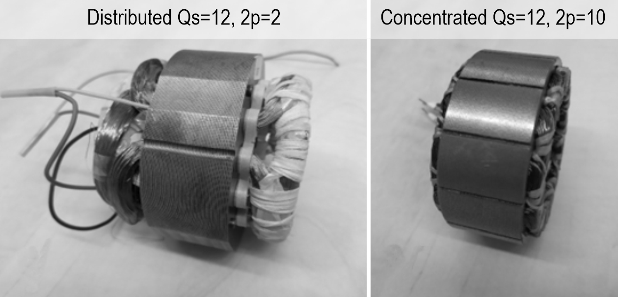
Fig. 7 Stator stack with three-phase winding
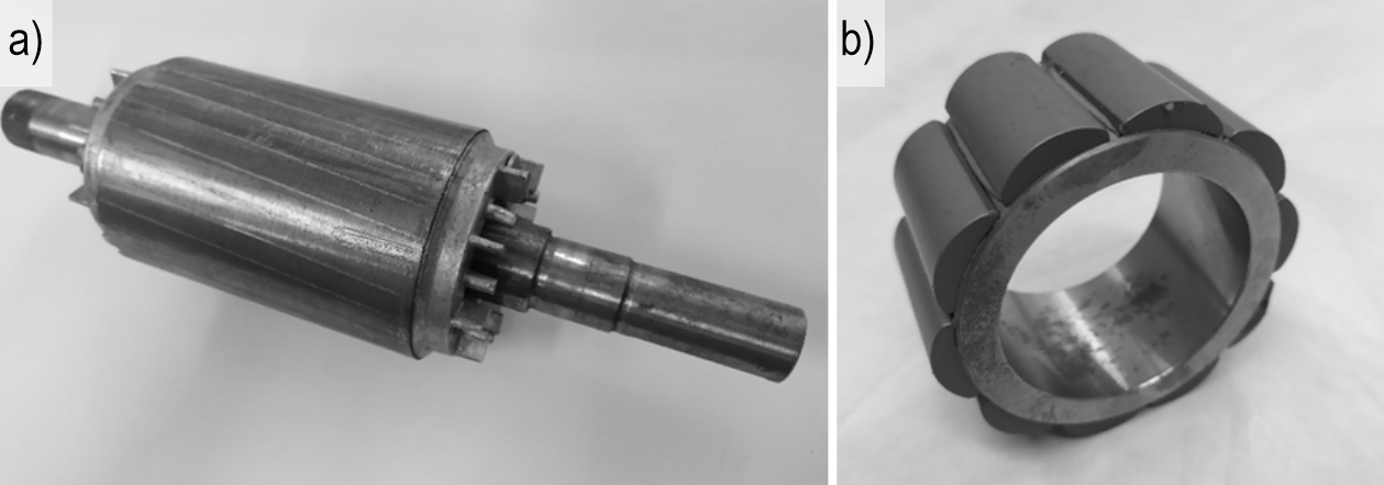
Fig. 8 a) Squirrel-cage rotor of an asynchronous motor; b) rotor (without shaft) of a synchronous motor with PM
The main difference between IM and PMSM is in the rotor. The rotor stack of an asynchronous motor is composed of metal sheets and is most often equipped with a cage winding, usually made of aluminum, Fig. 8a. In a PMSM, the rotor yoke can be made of solid steel or metal sheets, and permanent magnets (PM) are placed on the rotor. Permanent magnets can be either on the surface of the rotor, Fig. 8b, or they can be nested (inserted) inside the rotor stack. The location of the magnets inside the rotor is particularly important when de-excitation of the electric motor is required to increase the achievable speed range.
Permanent magnets generate a magnetic field in the PMSM without the need for input power. With IM, the electric motor must be excited from the stator side by means of the magnetizing current passing through the stator winding. This magnetizing current then creates losses in the stator winding.
The rotor speed of an asynchronous motor must always be lower than synchronous speed. This speed difference allows voltage to be induced into the rotor and create currents in the rotor cage. The rotor currents create a rotating magnetic field in the rotor, which rotates synchronously with the rotating magnetic field of the stator and creates a torque. However, the rotor current also creates losses in the IM rotor cage. Losses in the PMSM rotor do not occur when considering only the fundamental (working) harmonic of the magnetic field. In practice, however, certain losses in the PMSM rotor may arise due to the existence of additional harmonics of the magnetic field in the air gap of the electric motor, which induce eddy currents in the electrically conductive PM material (NdFeB, SmCo).
From the above design differences, it can be deduced that, in general, lower losses can be expected at the nominal working point for PMSM, and therefore higher efficiency than for IM.
Furthermore, a higher torque-to-volume, or torque-to-weight, ratio can be expected for PMSM. This is also evident from the values listed in Table 2, which are taken from the literature (Pyrhonen et al. 2013). Based on (Pyrhonen et al. 2013), PMSM can assume up to 1/3 smaller volume of active parts of the electric motor than IM. This is mainly due to the higher expected magnetic flux density in the air gap for PMSM (using PM from rare earths) and the higher cos (ξ), where ξ is spatial phase shift between the fundamentals of the distributions of magnetic flux density and linear current density.
Table 2 Tangential stresses for IM and PMSM dimensioning; adapted from Pyrhonen et al. (2013)
|
Closed IM |
PMSM |
|
|
Linear current density, ARMS [kA] |
30–65 |
35–65 |
|
Magnetic induction in the air gap, Bδ1max [T] |
0.7–0.9 |
0.85–1.05 |
|
Tangential voltage (avg), σFtan [Pa] |
21,500 |
33,500 |
|
Estimated power factor, cos (ξ) [-] |
0.8 |
1 |
It is therefore clear from the above that PMSM is more suitable for replacing the slewing bearing powertrain system, despite the higher price. As this application requires starting the motor from zero speed to rated speed at which the electric motor operates over the full range of torques, its disadvantage of problematic flux-weakening is not significant and the above advantages far outweigh those of IM.
The same engine concept is also used, for example, in the electric excavator and in the electric part of the hybrid drive of the harvester as stated in (Nevrly et al. 2022, Procházka et al. 2019). The definition of the requirements for an electric motor for the hydraulic slewing gear of the hravestor crane and the subsequent selection of a suitable motor was also based on the fact that it is a slewing gear of the harvester with a hybrid drive and the battery of the hybrid system can be used as a source of DC voltage for the inverter that feeds the electric motor, which is designed to allow the use of batteries based on LiFePo4 (Lithium Iron Phosphate), LTO (Lithium Titanate Oxide), or TPPL (Thin plate pure lead). The choice of a specific technology is determined on one hand by the destination of the harvester operation and on the other hand by the size of the total purchasing cost, where the price of the accumulator is not negligible. As it is the case with the price of the LTO battery, which, despite its high price and larger built-in dimensions, than, for example, the LiFePo4 battery, has the best operating characteristics and the absolute longest service life when cyclically loaded with large currents. Due to the nature of the entire drive system, the use of ultracapacitors was not considered. Compared to accumulators, no manufacturers offer cells with sufficient capacity at a sufficiently high voltage, and their use entails the necessity of constructing an additional DC/DC converter in order to fully utilize their capacity.
5. Conclusions
As part of the research, it was found that the maximum power needed to swing the harvester crane was 9720 W. During this maximum, the torque reached 187.98 Nm. However, the average power required to swing the hydraulic crane was only 2472 W at a torque of 47.81 Nm. These values resulted in the use of a synchronous electric motor with permanent magnets and harmonic induced voltage with a nominal speed of 2000 rpm and a power of 3246 W. Fitting the engine would, however, require the creation of a planetary gearbox with fast input speeds, which would be reduced to slow output speeds. However, the research results demonstrate the possibility of using an electric motor to swing the hydraulic crane during the work cycle of the harvester. In addition, there are prerequisites for the use of energy recovery from crane braking, which could lead to a reduction in fuel consumption and emissions.
Acknowledgments
The authors gratefully acknowledge funding from the Specific Research on BUT FSI-S-23-8235.
6. References
Bucherl, D., Nuscheler, R., Meyer, W., Herzog, H., 2008: Comparison of electrical machine types in hybrid drive trains: Induction machine vs. permanent magnet synchronous machine. Proceedings of the 18th International Conference on Electrical Machines, Vilamoura, Portugal, September 6–9, 1–6 p.
Di Blasio, G., Agarwal, A.K., Belgiorno, G., Shukla, P.C., 2022: Introduction to Clean Fuels for Mobility. In Clean Fuels for Mobility, 1st ed.; Agarwal A.K., Eds.; Springer Nature: Berlin, Germany, 3–7.
Edlund, J., Bergsten, U., Löfgren, B., 2012: Effects of two different forwarder steering and transmission drive systems on rut dimensions. Journal of Terramechanics 49(5): 291–297. https://doi.org/10.1016/j.jterra.2012.03.004
Engström, J.,: Modular battery swap system as an enabler for fossilfree mobile work machines. Available online: https://www.ri.se/en/what-we-do/projects/modular-battery-swap-system-as-an-enabler-for-fossilfree-mobile-work-machines (accessed on 13 December 2022)
Einola, K., 2013: Prestudy of a Power Management of a Cut-To-Length Forest Harvester with a Hydraulic Hybrid System. Proceedings of the 13th Scandinavian International Conference on Fluid Power, Linköping, Sweden, June 3–5, 71–83 p.
Einola, K., Kivi, A., 2015: First experimental results of a hydraulic hybrid concept system for a cut-to-length forest harvester. Proceedings of the 14th Scandinavian International Conference on Fluid Power, Tampere, Finland, May 20–22, 52–64.
Elforest Technologies: Ponsse Ergo with Elturbo. Available online: https://elforest.se/news.php?lang=en&number=5&category=2&start_from=15 (accessed on 13 December 2022)
Elmia AB: Battery-powered combi machine and new »big« harvesting head attract the crowds at Malwa's stand. Available online: https://www.elmia.se/en/wood/for-visitors/news/batteridriven-kombimaskin-och-ny-stor-skordare-lockar-storpublik-i-malwas-monter/ (accessed on 13 December 2022)
Fabiś, P., Flekiewicz, M., 2021: Optimalisation of the SI Engine Timing Advance Fueled by LPG. Sci. J. Silesian Univ. Technol. Ser. Transp. 111: 33–41. https://doi.org/10.20858/sjsutst.2021.111.3
Robert Easton Ltd. PONSSE EV1: A Technological breakthrough. Available online: https://forestmachinemagazine.com/ponsse-ev1-a-technological-breakthrough/ (accessed on 13 December 2022)
Górski, K., Sander, P., Longwic, R., 2018: The Assessment of Ecological Parameters of Diesel Engine Supplied with Mixtures of Canola Oil with N-Hexane. IOP Conference Series: Materials Science and Engineering 421(4): 042025. https://doi.org/10.1088/1757-899X/421/4/042025
Haugh, J. EV1: First look at Ponsse's new electric forwarder concept. Available online: https://www.forestryjournal.co.uk/news/20667734.ev1-first-look-ponsses-new-electric-forwarder-concept/ (accessed on 13 December 2022)
Hendershot, J.R., Miller, T.J.E., 2010: Design of Brushless Permanent-Magnet Motors, 3rd ed.: Motor Design Books LLC: Venice, USA, 822 p.
Hissa, M., Niemi, S., Sirviö, K., Niemi, A., Ovaska, T., 2019: Combustion Studies of a Non-Road Diesel Engine with Several Alternative Liquid Fuels. Energies 12(12): 2447. https://doi.org/10.3390/en12122447
Hunicz, J., Mikulski, M., Shukla, P.C., Gęca, M.S., 2022: Partially Premixed Combustion of Hydrotreated Vegetable Oil in a Diesel Engine: Sensitivity to Boost and Exhaust Gas Recirculation. Fuel 307: 121910. https://doi.org/10.1016/j.fuel.2021.121910
Hurtová, I., Sejkorová, M., Verner, J., 2019: A Study of Diesel Particulate Filter Impact on Engine Oil Quality. In Proceedings of the Transport Means–Proceedings of the International Conference, Palanga, Lithuania, October 2–4, 691–695 p.
Johnsen, T.,: Logset 12H GTE Hybrid-electric Harvester. Available online: https://www.forestry.com/editorial/logset-12h-gte-electric-hybrid-harvester/ (accessed on 13 December 2022)
Jonsson, P.,: Malwa – it's electrifying! Available online: https://www.forestry.com/editorial/malwa-its-electrifying/ (accessed on 13 December 2022b)
Jonsson, P.,: Ponsse EV1 – it's electrical!. Available online: https://www.forestry.com/editorial/ponsse-ev1-electrical/ (accessed on 13 December 2022a)
Kammermann, J., Freiberger, R., Mahat, D., Herzog, H.G., 2015: Assumptions for an Early Stage Comparative Analysis of Induction Machines and Permanent Magnet Synchronous Machines. Proceedings of the IEEE Vehicle Power and Propulsion Conference, Montreal, Canada, October 19–22, 1–5 p.
Khan, M.I., Yasmin, T., Shakoor, A., 2015: Technical Overview of Compressed Natural Gas (CNG) as a Transportation Fuel. Renew. Sustain. Energy Rev. 51: 785–797. https://doi.org/10.1016/j.rser.2015.06.053
Klvač, R., Ward, S., Owende, P.M.O., Lyons, J., 2003: Energy Audit of wood harvesting systems. Scandinavian Journal of Forest Research 18(2): 176–183. https://doi.org/10.1080/02827580310003759
Labaj, J., Barta, D., 2006: Unsteady Flow Simulation and Combustion of Ethanol in Diesel Engines. Communications 8(2): 27–3. https://doi.org/10.26552/com.C.2006.2.27-37
Lajunen, A., Suomela, J., Pippuri, J., Tammi, K., Lehmuspelto, T., Sainio, P., 2016: Electric and Hybrid Electric Non-Road Mobile Machinery – Present Situation and Future Trends. World Electric Vehicle Journal 8(1): 172–183. https://doi.org/10.3390/wevj8010172
Langshaw, L., Ainalis, D., Acha, S., Shah, N., Stettler, M.E.J., 2020: Environmental and Economic Analysis of Liquefied Natural Gas (LNG) for Heavy Goods Vehicles in the UK: A Well-to-Wheel and Total Cost of Ownership Evaluation. Energy Policy 137: 111161. https://doi.org/10.1016/j.enpol.2019.111161
Lesprom Network: New 100% electric logging machine of Malwa Forest operates for two hours on single charge. Available online: https://www.lesprom.com/en/news/New_100_electric_logging_machine_of_Malwa_Forest_operates_for_two_hours_on_single_charge_103491/ (accessed on 13 December 2022)
Lin, T., Wang, Q., Hu, B., Gong, W., 2010: Development of hybrid powered hydraulic construction machinery. Automation in Construction 19(1): 11–19. https://doi.org/10.1016/j.autcon.2009.09.005
Logset Oy. Logset 12H GTE hybrid. Available online: https://logset.fi/hybrid-technology/ (accessed on 13 December 2022)
Małek, A., Dudziak, A., Stopka, O., Caban, J., Marciniak, A., Rybicka, I., 2022: Charging Electric Vehicles from Photovoltaic Systems–Statistical Analyses of the Small Photovoltaic Farm Operation. Energies 15(6): 2137. https://doi.org/10.3390/en15062137
Mergl, V., 2022: Multicriteria analysis of harvester use with support drive system in thinning. Dissertation thesis, Mendel University in Brno, Czech Republic.
Mizik, T., 2022: Sustainable Fuels in Private Transportation–Present and Future Potential. In Clean Fuels for Mobility, 1st ed.; Agarwal A.K., Eds.; Springer Nature: Berlin, Germany, 9–26 p.
Pellegrino, G., Vagati, A., Boazzo, B., Guglielmi, P., 2012: Comparison of Induction and PM Synchronous Motor Drives for EV Application Including Design Examples. IEEE Transactions on Industry Applications 48(6): 2322–2332. https://doi.org/10.1109/TIA.2012.2227092
Nevrly, J., Fichta, M., Jurik, M., Nemec, Z., Prochazka, P., Koutny, D., Petrovic, R., 2022: New systems of energy recovery and eletric.hydraulic battery mobile drive. MM Science Journal 3: 5795–5800. https://doi.org/10.17973/MMSJ.2022_10_2022073
Ponsse Plc. Ponsse launches new technology: an electric forest machine. Available online: https://www.ponsse.com/company/news/-/asset_publisher/P4s3zYhpxHUQ/content/ponsse-launches-new-technology-an-electric-forest-machine#/ (accessed on 13 December 2022)
Procházka, P., Pazder, I., Cipín, R., 2019: Hybrid Tree Harvester Machine with Battery Powered Hydro-Electric Drive. ECS Transactions 95(1): 349–354. https://doi.org/10.1149/09501.0349ecst
Rayapureddy, S.M., Matijošius, J., Rimkus, A., Caban, J., Słowik, T., 2022: Comparative Study of Combustion, Performance and Emission Characteristics of Hydrotreated Vegetable Oil–Biobutanol Fuel Blends and Diesel Fuel on a CI Engine. Sustainability 14(12): 7324. https://doi.org/10.3390/su14127324
Pyrhonen, J., Jokinen, T., Hrabcova, V., 2013: Design of Rotating Electrical Machines, 2nd ed.; Wiley, New York, USA, 616 p.
Sejkorová, M., Šarkan, B., Verner, J., 2017: Efficiency Assessment of Fuel Borne Catalyst. MATEC Web of Conferences 134: 00051. https://doi.org/10.1051/matecconf/201713400051
Sellgren, U. Engineerimg Education for Industrial Innovation. Available online: https://www.researchgate.net/publication/266291963_ENGINEERING_EDUCATION_FOR_INDUSTRIAL_INNOVATION (accessed on 13 December 2022)
Stoddart, N., 2010: El-forest hybrid forwarder. Forestry Journal 10(7): 20–21.
Wasilewski, J., Szyszlak-Bargłowicz, J., Zając, G., Szczepanik, M., 2020: Assessment of CO2 Emission by Tractor Engine at Varied Control Settings of Fuel Unit. Agricultural Engineering 24(4): 105–115. https://doi.org/10.1515/agriceng-2020-0040
Zhu, Z.Q., Howe, D., 2007: Electrical Machines and Drives for Electric, Hybrid, and Fuel Cell Vehicles. Proceedings of the IEEE 95(4):746–765. https://doi.org/10.1109/JPROC.2006.892482
© 2023 by the authors. Submitted for possible open access publication under the
terms and conditions of the Creative Commons Attribution (CC BY) license (http://creativecommons.org/licenses/by/4.0/).
Authors' addresses:
Václav Mergl, PhD *
e-mail: Vaclav.Mergl1@vutbr.cz
Petr Procházka, PhD
e-mail: prochazkap@vut.cz
Lukáš Ziezinger, PhD
e-mail: Lukas.Zeizinger@vutbr.cz
Ondřej Vítek, PhD
e-mail: viteko@vut.cz
Brno University of Technology
Antonínská 548/1
601 90 Brno
CZECH REPUBLIC
Miroslav Nagy, Ing.
e-mail: miroslav.nagy@stuba.sk
Ladislav Gulan, PhD
e-mail: ladislav.gulan@stuba.sk
Slovak Technical University
Bratislava Vazovova 5
812 43 Bratislava 1
SLOVAK REPUBLIC
* Corresponding author
Received: May 21, 2023
Accepted: December 12, 2023
Original scientific paper